Variable-wavelength filter and variable-wavelength laser

a variable-wavelength laser and filter technology, applied in the field of optical filters, can solve the problems of not being able to increase the output of lasers, and achieve the effects of reducing manufacturing costs, improving frequency modulation efficiency, and increasing laser outpu

Inactive Publication Date: 2009-05-14
NEC CORP
View PDF3 Cites 99 Cited by
  • Summary
  • Abstract
  • Description
  • Claims
  • Application Information

AI Technical Summary

Benefits of technology

[0043]In the variable-wavelength filter according to the present invention, the optical circuit component divides and inputs the light to the loop waveguide, and the loop waveguide loops and returns only the light at an overlapping wavelength of the transmission characteristics of at least two wavelength selecting filters. Since a loss due to the optical filters is small and there is not a loss caused by a highly reflecting film, the output of the laser can be increased. The manufacturing cost is reduced because there is no step of forming a highly reflecting film. As the entire waveguide length is shorter than heretofore, the oscillation mode of the laser is stabilized, and the frequency modulation efficiency is improved.

Problems solved by technology

The first problem is that it is not suitable for increasing the output of the laser.

Method used


Image

  • Variable-wavelength filter and variable-wavelength laser
  • Variable-wavelength filter and variable-wavelength laser
  • Variable-wavelength filter and variable-wavelength laser

Examples


1st exemplary embodiment

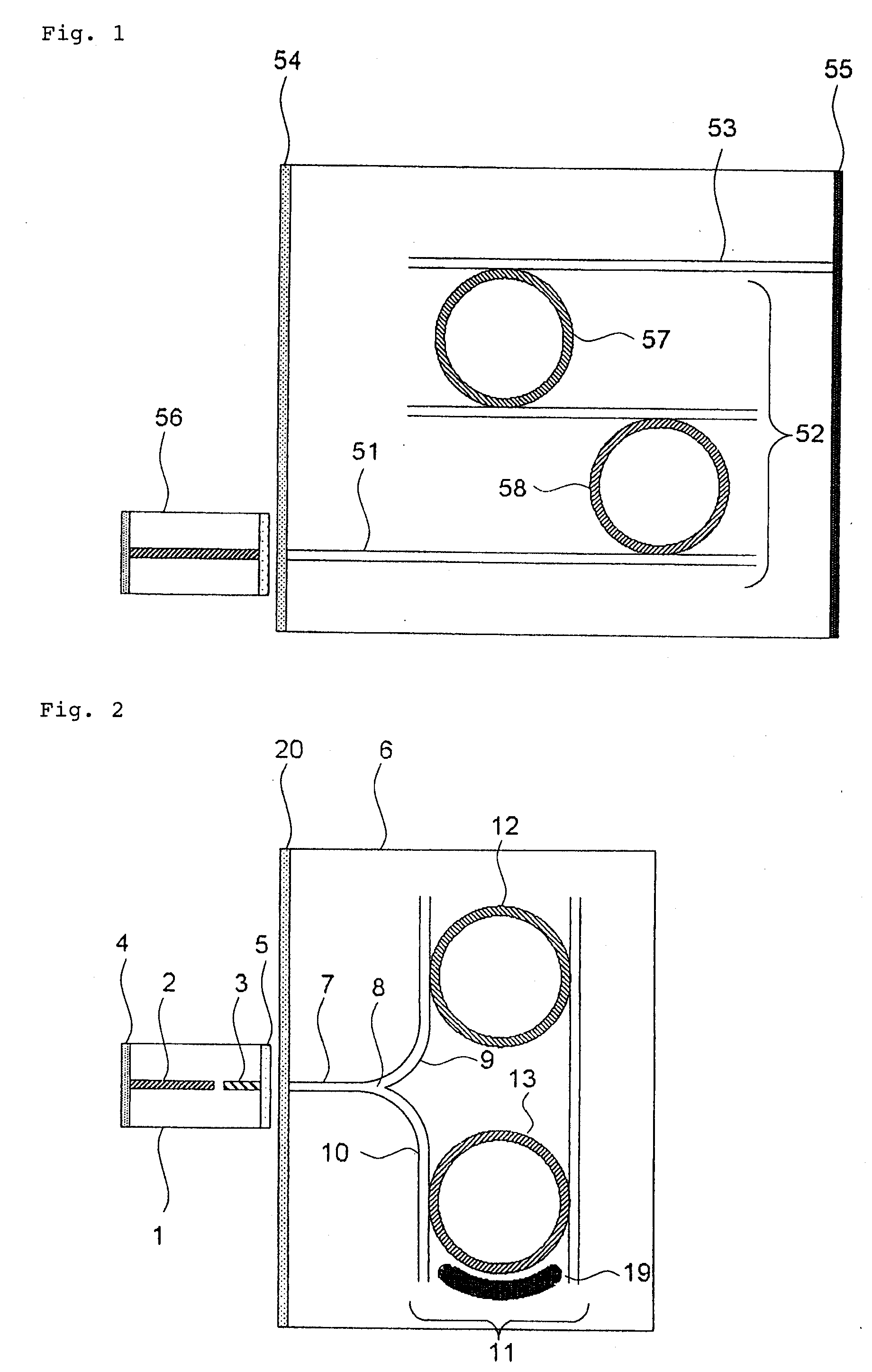
[0059]FIG. 2 is a schematic view showing the structure of an external-resonator variable-wavelength laser according to a first exemplary embodiment. As shown in FIG. 2, the external-resonator variable-wavelength laser basically comprises semiconductor device 1 and variable-wavelength filter substrate 6.

[0060]Semiconductor device 1 includes phase adjusting region 3 integrated as a passive component in combination with semiconductor optical amplifier 2 as an active component. Semiconductor device 1 has an optical output side where semiconductor optical amplifier 2 is located. Lowly reflecting coating 4 (having a reflectance ranging from 1% to 10%) is applied to the end face of the optical output side. Semiconductor device 1 has an external resonator side where phase adjusting region 3 is located. Nonreflecting coating (1% or less) is applied to the end face of the external resonator side. Semiconductor device 1 may have an optical output side where phase adjusting region 3 is located....


PUM


Abstract

Only the light at an overlapping wavelength of the transmission characteristics of at least two wavelength selecting filters is looped, and at least one of the wavelength selecting filters varies a selected wavelength. Since a loss due to the optical filters is small and there is not a loss caused by a highly reflecting film, the output of an external-resonator variable-wavelength laser can be increased. Optical circuit component (8) divides light input from external device (1) into at least two ports. Loop waveguide (11) interconnects at least ports (9, 10) divided by optical circuit component (8) in the form of a loop. At least two first wavelength selecting filters (12, 13) are inserted in series in a path of loop waveguide (11), and have periodic transmission characteristics on a frequency axis which are different from each other. At least one of first wavelength selecting filters (12, 13) varies the selected wavelength.

Description

TECHNICAL FIELD[0001]The present invention relates to an optical filter which is capable of selecting a desired laser oscillation wavelength, and a variable-wavelength laser incorporating such an optical filter.BACKGROUND ART[0002]In recent years, as the Internet has been quickly finding widespread use, the communication traffic has grown to the extent that there has been a demand for optical communication systems of greater capacity. To meet such a demand, attempts have been made to increase the number of channels by increasing the transmission rate per channel in the system and also by employing the optical WDM (Wavelength Division Multiplexing) process. The WDM allows a plurality of optical signals having different carrier wavelengths to be transmitted simultaneously over a single optical fiber.[0003]According to the WDM, the communication capacity increases depending on the number of carrier wavelengths (channels) to be multiplexed. For example, if data are modulated at 10 gigab...

Claims


Application Information

Patent Timeline
Patent Type & Authority Applications(United States)
IPC IPC(8): H01S3/10G02B6/10
CPCG02B6/12007G02F1/313G02F2203/15G02F2203/585H01S5/142H01S5/0687H01S5/101H01S5/1032H01S5/02248H01S5/02325
Inventor SATO, KENJIDE MERLI, JANMIZUTANI, KENJISUDO, SHINYAKUDO, KOJIYAMAZAKI, HIROYUKI
Owner NEC CORP
Why Eureka
Try Eureka