Method for making silica nanoparticles by flame spray pyrolysis adopting two-fluid nozzle

a technology of flame spray pyrolysis and silica nanoparticles, which is applied in the field of making nanoparticles, can solve the problems of low yield of silica nanoparticles, large amount of energy consumed, and hardly applicable in the industry

Inactive Publication Date: 2009-05-14
KOREA INST OF GEOSCI & MINERAL RESOURCES
View PDF5 Cites 40 Cited by
  • Summary
  • Abstract
  • Description
  • Claims
  • Application Information

AI Technical Summary

Benefits of technology

[0012]Accordingly, the present invention has been made to solve the above-mentioned problems occurring in the prior art, and an object of the present invention is to provide a method for making silica nanopart...

Problems solved by technology

However, pulse laser method shows a low yield of silica nanoparticles, and thus is hardly applicable in the industry.
According to these methods, however, a large amount of energy is con...

Method used


Image

  • Method for making silica nanoparticles by flame spray pyrolysis adopting two-fluid nozzle
  • Method for making silica nanoparticles by flame spray pyrolysis adopting two-fluid nozzle
  • Method for making silica nanoparticles by flame spray pyrolysis adopting two-fluid nozzle

Examples


example 1

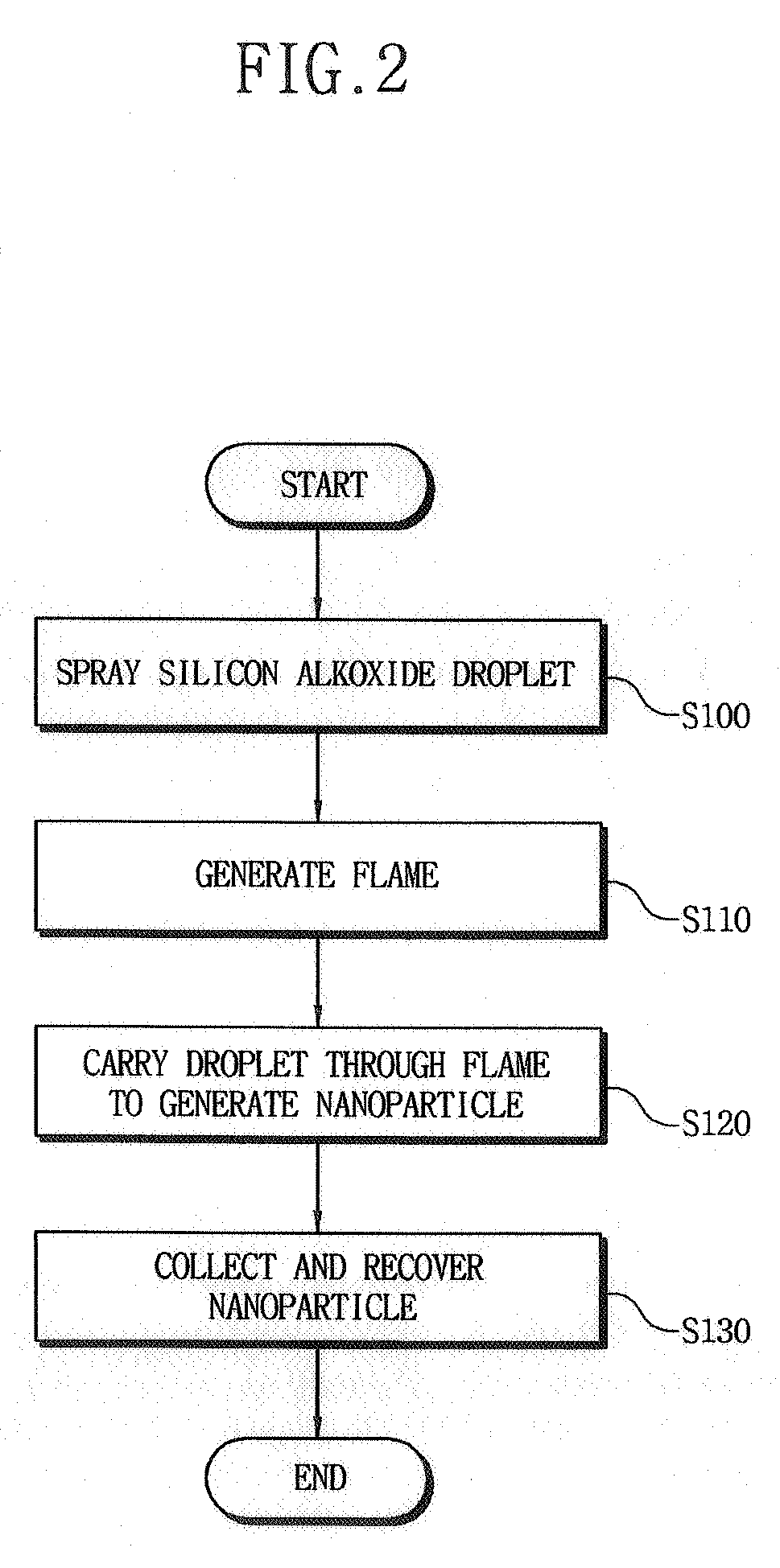
[0038]Example 1 was aimed to adjust the size of resultant particles by varying the pressure of dispersed air for micronizing liquid source material during the production of nanoparticles.

[0039]An experiment was carried out to make silica nanoparticles, in which silicon alkoxide (TEOS) mixed with ethanol were delivered through a flame under the following conditions.

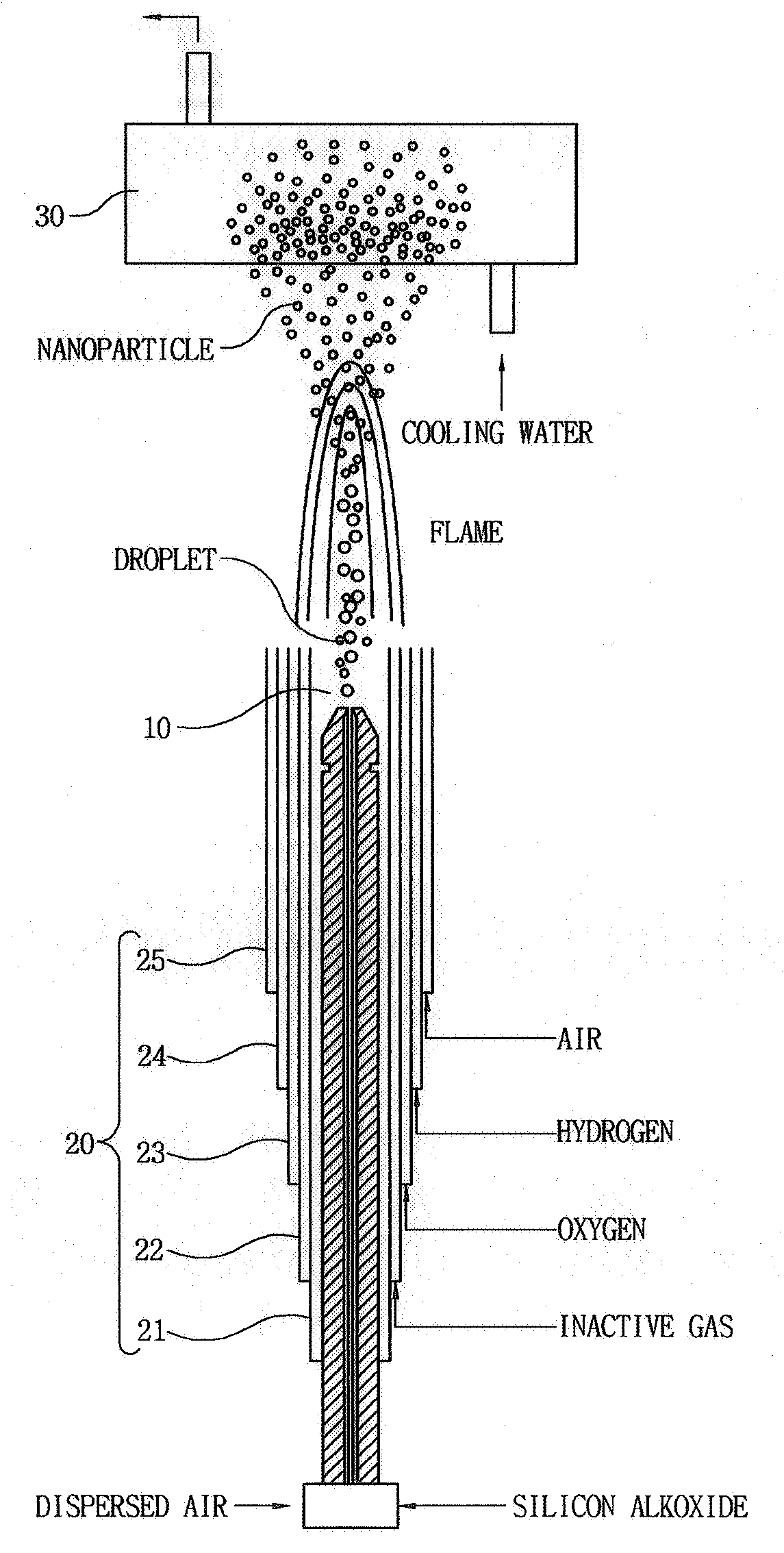
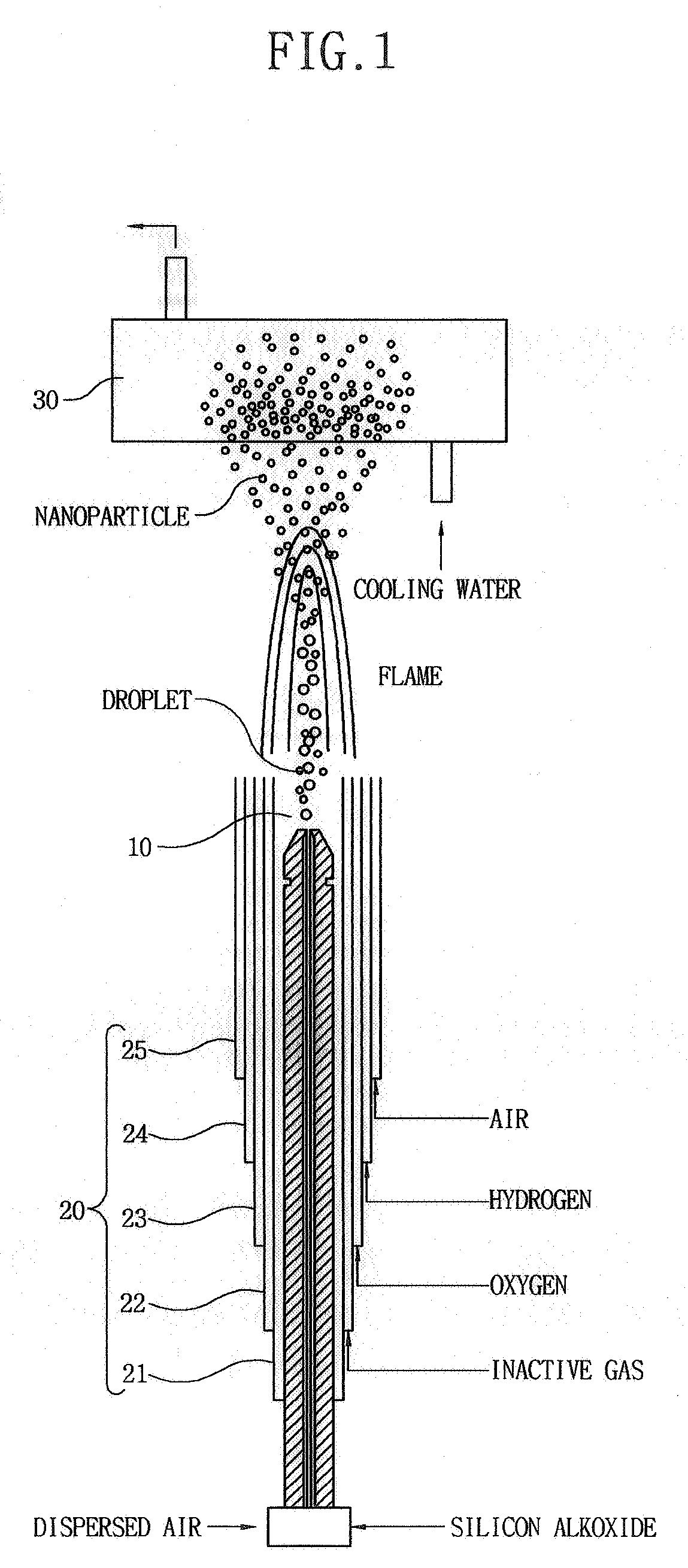
[0040]A liquid sample or TEOS was injected into the droplet spray 10 as shown in FIG. 1, where it was liquefied with dispersed air under high pressure. Then, the liquefied TEOS was flown into the first tube 21 in the center of the burner 20, and Ar, H, oxygen and air were blown respectively in their order into the second to fifth tubes 22 to 23 of the dispersion type burner 20, thereby producing flame.

[0041]Describing the flow rate of gas introduced into the flame reactor, dispersed air was blown into the first tube 21 of the burner 20 having the first to fifth tubes 21 to 25, at a volume fraction of 2% to 3% in the entire...

example 2

[0044]Example 2 was aimed to adjust the size of resultant particles by injecting a reactive material into a hot flame with different concentrations of 2.1×10⁻⁴ mol / l, 3.3×10⁻⁴ mol / l and 4.8×10⁻⁴ mol / l while maintaining constantly the pressure of dispersed air for micronizing liquid source material during the production of nanoparticles.

[0045]Describing the flow rate of gas blown into the flame reactor, the pressure of the dispersed air introduced into the first tube of the burner was maintained constantly at 3.0 kgf / cm2, which is 1% to 2% in volume of the entire flow rate of gas, in order to make a TEOS reactive material into fine droplets having molarities of 2.0×10⁻⁴ mol / l, 3.3×10⁻⁴ mol / l and 4.8×10⁻⁴ mol / l. In addition, Ar gas at 7% in volume fraction was blown into the second tube 22, hydrogen gas at 14% in volume fraction was blown into the third tube 23, oxygen gas at 21% in volume fraction was blown into the fourth tube 24, and air at 56% to 57% in volume fraction was blown i...

example 3

[0048]Example 3 was aimed to adjust the size of resultant particles by adjusting the flow rate of hydrogen gas used as fuel to 3% in volume fraction and then changing the flow rate of a TEOS reactive material.

[0049]Describing the flow rate of gas blown into the flame reactor, the pressure of the dispersed air introduced into the first tube of the burner was maintained constantly at 3.0 kgf / cm2, which is 2% in volume of the entire flow rate of gas, in order to make the TEOS reactive material into fine droplets having molarities of 2.1×10⁻⁴ mol / l, 3.3×10⁻⁴ mol / l and 4.8×10⁻⁴ mol / l. In addition, Ar gas at 8% in volume fraction was blown into the second tube 22, hydrogen gas at 3% in volume fraction was blown into the third tube 23, oxygen gas at 24% in volume fraction was blown into the fourth tube 24, and air at 63% in volume fraction was blown into the fifth tube 25. With these conditions, silica nanoparticles were produced.

[0050]FIG. 5 illustrates TEM photographs of nanoparticles pr...


PUM


Abstract

The invention relates to a method for making silica nanoparticles using a flame reactor, which includes a droplet spray having a two-fluid nozzle and a burner of a quintuple tube structure. In this method, droplets of silicon alkoxide as liquid Si compound are sprayed through the droplet spray of the flame reactor. A flame is generated by the flow of inert gas, oxygen, hydrogen and air simultaneously into the burner of the flame reactor. The liquid Si compound is delivered through the flame of the burner to produce silica nanoparticles having a mean particle size ranging from 9 nm to 68 nm. Resultant nanoparticles are collected and recovered in a particle collector. The droplets sprayed under high pressure from a silicon alkoxide solution are directly oxidized in the flame, thereby producing spherical silica nanoparticles.

Description

BACKGROUND OF THE INVENTION[0001]1. Field of the Invention[0002]The present invention relates to a method for making nanoparticles, and more particularly to a method for making silica nanoparticles by flame spray pyrolysis adopting a two-fluid nozzle, which sprays droplets under high pressure from a silicon alkoxide solution to directly oxidize in a flame thereby producing spherical silica nanoparticles.[0003]2. Description of the Prior Art[0004]In general, nanoparticles refer to particles having a size 100 nm or less, which are mainly used as advanced materials due to high specific area per mass and novel functions.[0005]Silica (SiO2) particles are adopted in various applications such as fillers of Epoxy display and semiconductor Molding Compound (EMC), fillers of cosmetics and copy machine toner, components of paint and ink for improving endurance and inducing diffused reflection, raw materials of optical fibers, ceramic ware and glasses.[0006]Examples of technologies for making s...

Claims


Application Information

Patent Timeline
IPC IPC(8): C01B33/12
CPCC01B33/18Y10S977/84Y10S977/895Y10S977/896
Inventor CHANG, HAN KWONJANG, HEE DONG
Owner KOREA INST OF GEOSCI & MINERAL RESOURCES
Why Eureka
Try Eureka