Method of measurement, control, and regulation for the solar thermal hybridization of a fossil fired rankine cycle

a solar thermal hybridization and rankine technology, applied in the direction of process and machine control, lighting and heating apparatus, instruments, etc., can solve the problems of inability to compete with solar rankine power generation systems, relatively high cost of solar thermal generation facilities, and inefficient efficiency

Inactive Publication Date: 2009-05-14
MARKRON TECH
View PDF10 Cites 84 Cited by
  • Summary
  • Abstract
  • Description
  • Claims
  • Application Information

AI Technical Summary

Benefits of technology

[0009]An aspect of at least one of the embodiments disclosed herein includes the realization that it would be advantageous to operate power generation systems which integrate solar heating differently under different conditions in order to meet specific power generation needs. The solar heating capabilities and output of a Rankine cycle power generation system can vary depending on, for example, the load forecast received from a grid regulating entity, weather forecasts (e.g. the amount of sunlight available on a given day), the expected costs of power generation, and the amount, if any, of any solar energy which has already been stored in a solar storage unit. It can often be desirable to run such power generation systems under maximum capacity, maximum efficiency, or a combination of both. Thus, there is a need for an operator control system, as well as operator controls and routines, which allow an operator to run the solar integrated system in different modes under different conditions to help ensure system stability and operation within the Rankine unit's limits.

Problems solved by technology

Such solar thermal generation facilities are relatively expensive, require the use of a fairly complex solar boiler, and are relatively inefficient due to the lower operating temperature of the working fluid compared to fossil fired cycles.
Thus, solar Rankine power generation systems cannot compete, in most cases, with traditional fossil fuel generated electrical energy.
Additionally, solar Rankine power generation systems cannot operate (without fossil-fuel back up or storage) during severe overcast or night hours.
While these methods provide some additional heat to the Rankine cycle, all have certain restrictions and cost disadvantages.

Method used


Image

  • Method of measurement, control, and regulation for the solar thermal hybridization of a fossil fired rankine cycle
  • Method of measurement, control, and regulation for the solar thermal hybridization of a fossil fired rankine cycle
  • Method of measurement, control, and regulation for the solar thermal hybridization of a fossil fired rankine cycle

Examples


Embodiment Construction

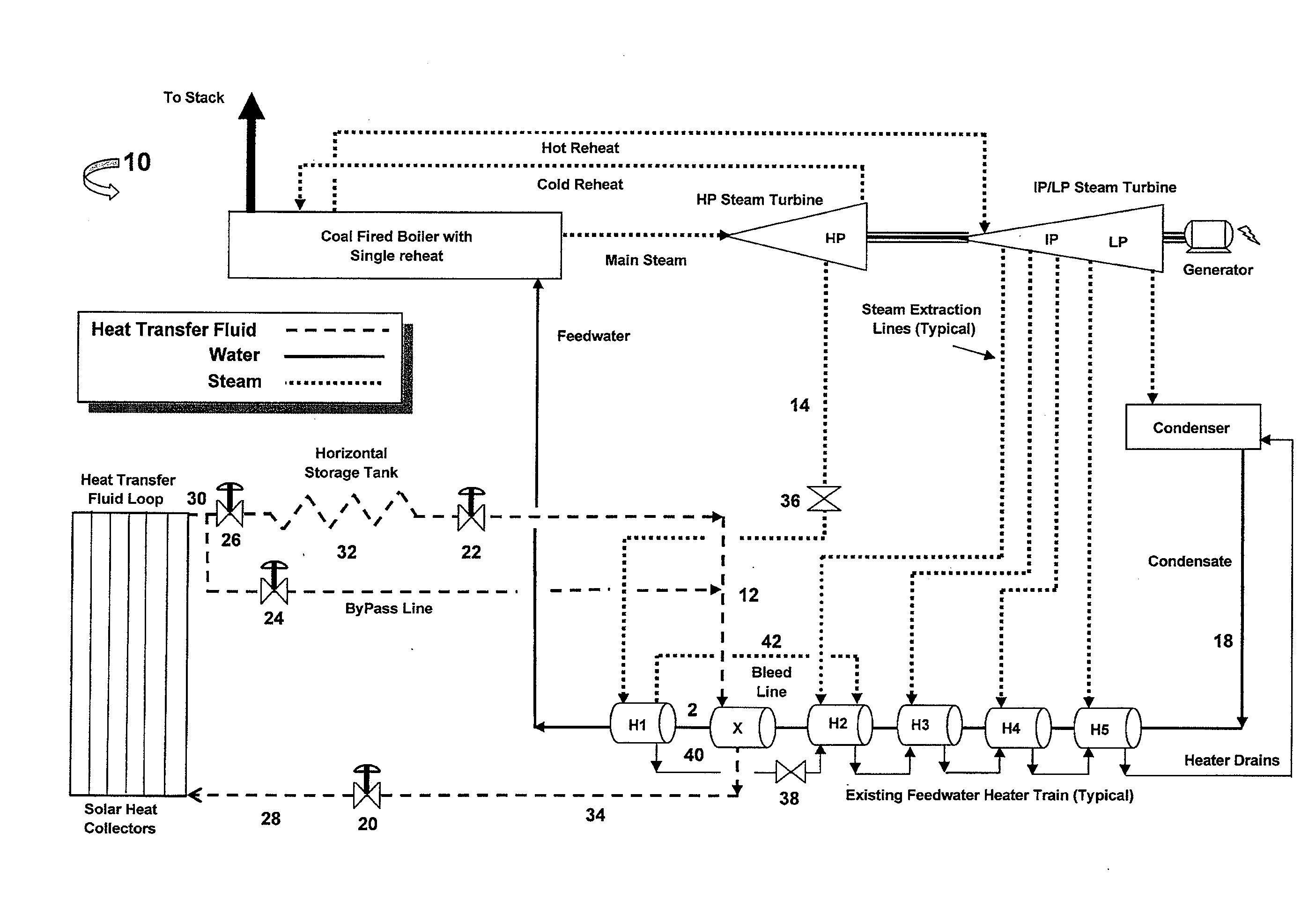
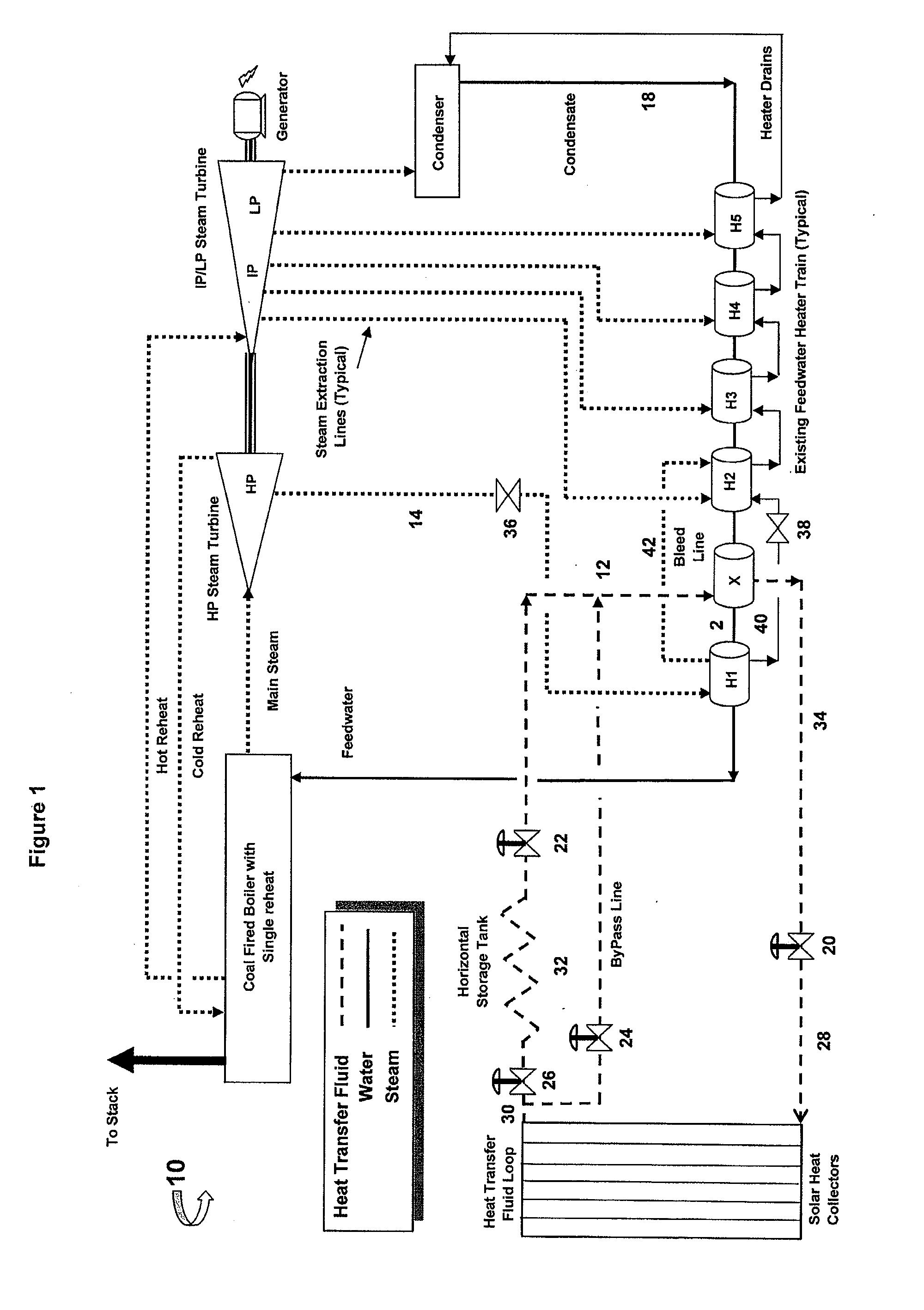
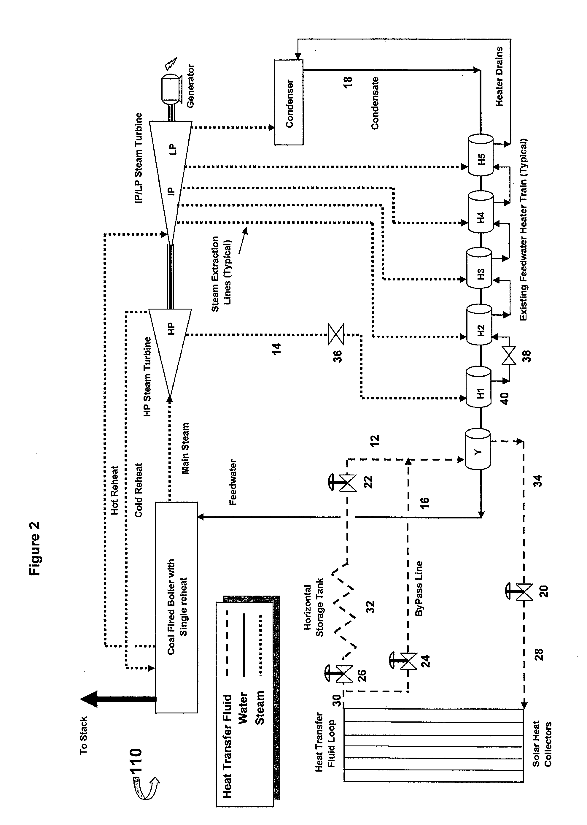
[0035]The embodiments disclosed herein are described in the context of a coal-fueled Rankine cycle power generation system using regenerative heating because the embodiments disclosed herein have particular utility in this context. However, the embodiments of the methods and control routines described herein can also be applied to other types of power generation systems, including but not limited to natural gas or nuclear fueled boiler power generation systems and other regenerative steam Rankine cycle power generation systems.

[0036]In general, and with reference to FIGS. 1-3, a Rankine cycle power generation system can generate power through the vaporization and condensation of a working fluid (e.g. feedwater) in a heat cycle. Vaporization of the feedwater is accomplished in a boiler, with energy provided by the combustion of a fossil fuel, such as by the burning of coal. The feedwater can be water, which, upon the addition of sufficient heat energy, can vaporize into water steam. ...


PUM


Abstract

A method of measurement, control, and regulation for a solar integrated Rankine cycle power generation system can include a central processing unit (CPU) which receives input from an operator and/or sensors regarding load forecast, weather forecast, system cost, and capacity or efficiency needs. The method can include activation, in various sequencing, of heat transfer fluid control valves, storage control valves, and at least one turbine control valve.

Description

CROSS-REFERENCE TO RELATED APPLICATIONS[0001]This application claims priority to U.S. Provisional Patent Application No. 61 / 002,447, entitled “METHOD OF MEASUREMENT, CONTROL, AND REGULATION FOR THE SOLAR THERMAL HYBRIDIZATION OF A FOSSIL FIRED RANKINE CYCLE” filed on Nov. 9, 2007, which is incorporated herein by reference in its entirety.BACKGROUND OF THE INVENTIONS[0002]1. Field of the Inventions[0003]The application relates generally to methods for control and regulation of power generation, and more specifically to methods for control and regulation of power generation systems which integrate a regenerative Rankine cycle power generation system with a solar energy collection system to achieve enhanced power generation efficiency.[0004]2. Description of the Related Art[0005]Rankine cycle power generation systems generate power by alternately vaporizing and condensing feedwater. In a typical Rankine cycle power plant, the feedwater is vaporized in a boiler to which heat energy is a...

Claims


Application Information

Patent Timeline
Patent Type & Authority Applications(United States)
IPC IPC(8): B60K16/00F01K7/16G05D9/12G06F1/28
CPCF22D1/003F01K7/40Y02T10/7072
Inventor SKOWRONSKI, MARK JOSEPHKINCAID, RONALD FARRIS
Owner MARKRON TECH
Why Eureka
Try Eureka