Gas turbine control device and gas turbine system

a control device and gas turbine technology, applied in process and machine control, lighting and heating apparatus, instruments, etc., can solve problems such as deterioration in combustion stability, heavy molecules, and eventual occurrence of combustion oscillation, so as to stabilize combustion, maintain combustion stability, and suppress combustion oscillation of combustor

Active Publication Date: 2009-05-14
MITSUBISHI POWER LTD
View PDF2 Cites 54 Cited by
  • Summary
  • Abstract
  • Description
  • Claims
  • Application Information

AI Technical Summary

Benefits of technology

[0029]According to the present invention, the state of operation of the gas turbine can be controlled based on the fuel composition or the heat capacity of the fuel to be supplied to the combustor. Consequently, it is possible to control the gas turbine in response to a change in the fuel composition caused by passage of time, to suppress combustion oscillation of the combustor, and to maintain combustion stability. In addition, since the relation between the fuel composition and the operation amount can be changed based on the history, it is possible to perform the control in response to aging of the gas turbine and to further stabilize combustion in the combustor.
[0030]Moreover, it is possible to obtain the measurement value of the fuel composition or the heat capacity of the fuel gas and to synchronize the timing of capturing the measurement value by the state grasping unit or by the state grasping unit and the combustion characteristic grasping unit with the timing of combusting the combusting gas from which this measurement value is obtained. Accordingly, it is possible to suppress combustion oscillation more reliably at the time of a change in the fuel composition and to maintain combustion stability more reliably. In addition, it is possible to shorten a sampling cycle (a measurement cycle) of the fuel gas by installing the multiple fuel characteristic detecting units and shifting the timing for measuring the fuel. Consequently, it is possible to improve a tracking performance relative to a change in the fuel composition or the heat capacity of the fuel gas, and thereby to maintain combustion stability more reliably.
[0031]Moreover, even when a fuel characteristic measuring unit such as a gas analyzer is not provided, it is possible to change the contents of a counter measure process so as to follow the change in the fuel characteristic by using the category of the fuel characteristic determined by the fuel characteristic estimating unit. Accordingly, it is possible to maintain combustion stability. Further, even in the case of operating the gas turbine for a long period of time, it is possible to judge the category of the fuel characteristic by correcting the ratio between the gas turbine output and the fuel flow rate by use of the deterioration characteristic of the gas turbine. Accordingly, it is possible to maintain combustion stability more reliably. In addition, the combustion characteristic grasping unit is provided for finding the relational expression indicating the combustion characteristic of the combustor from the current state of operation of the gas turbine confirmed by the state grasping unit on the basis of the category of the fuel characteristic determined by the fuel characteristic estimating unit, and the countermeasure determining unit determines the increase or decrease in the flow rate of at least one of the fuel flow rate and the air flow rate to the combustor by use of the relational expression indicating the combustion characteristic of the combustor. Accordingly, it is possible to improve accuracy of a characteristic analysis concerning combustion stability, and resultantly to maintain combustion stability while suppressing combustion oscillation at the time of the change in the fuel composition or the heat capacity.

Problems solved by technology

However, there is a possibility that fuel composition, the fuel flow rate, and the air flow rate in practice are deviated from those at the time of planning or at the time of test run adjustment due to variation in the composition or the heat capacity of the fuel gas to be supplied to the gas turbine or to secular changes such as deterioration in performance of a compressor or filter clogging, for example.
Attributed to such deviation, there arises a risk of deterioration in combustion stability and eventual occurrence of combustion oscillation which constitutes a major obstacle to operation of the gas turbine.
However, inside this fuel tank for storing the fuel gas, heavy molecules out of components constituting the fuel gas go down while light molecules go up over time.
As a result, the fuel composition of the fuel gas supplied to the gas turbine fluctuates in response to the residual amount of the fuel inside the fuel tank or to the time, whereby such a difference in the fuel composition generates a change in a combustive action in the combustor which may lead to reduction in the combustion stability.
Moreover, the fuel composition fluctuates largely in the case of using blast furnace gas as the fuel, for example, and similar reduction in the combustion stability may occur.

Method used


Image

  • Gas turbine control device and gas turbine system
  • Gas turbine control device and gas turbine system
  • Gas turbine control device and gas turbine system

Examples


first embodiment

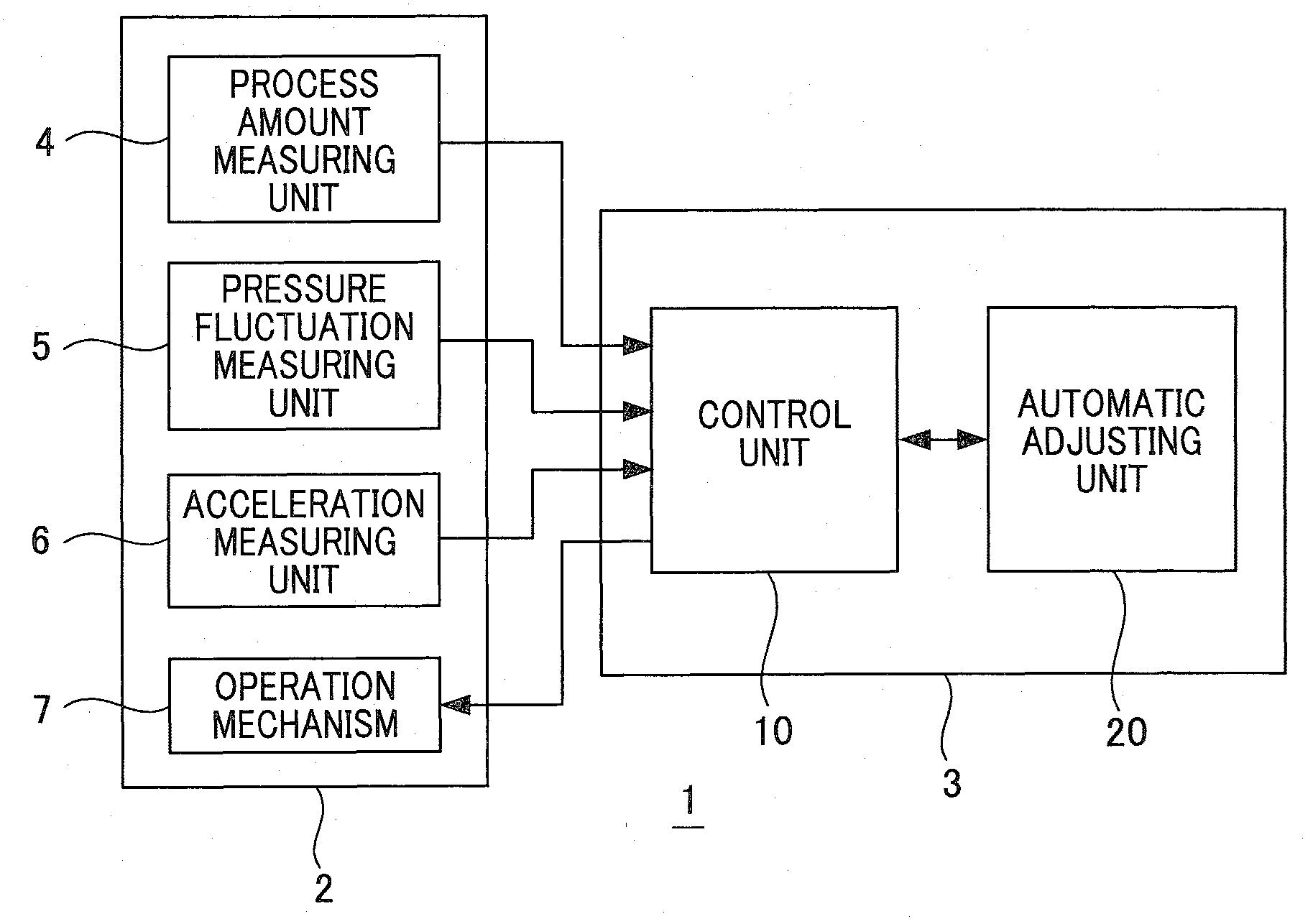
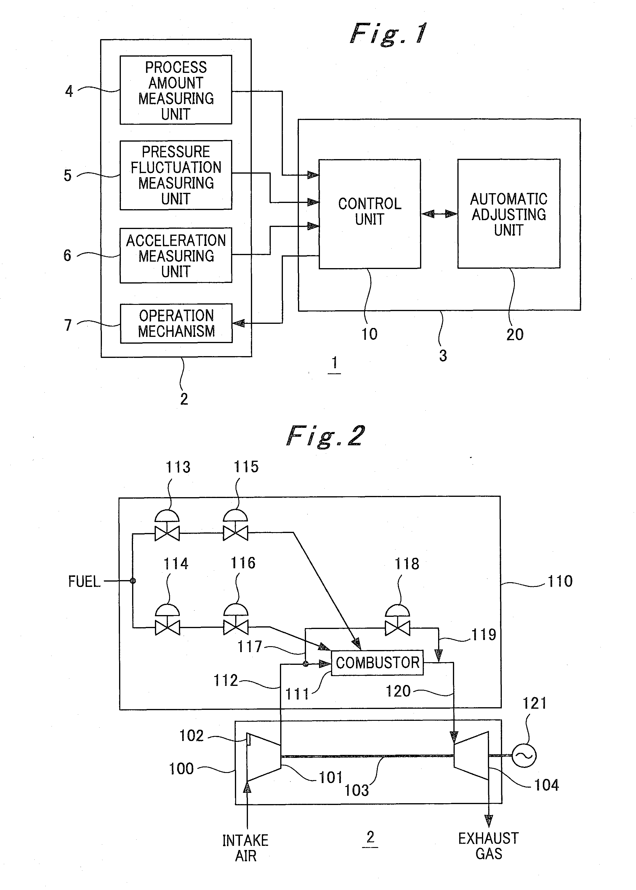
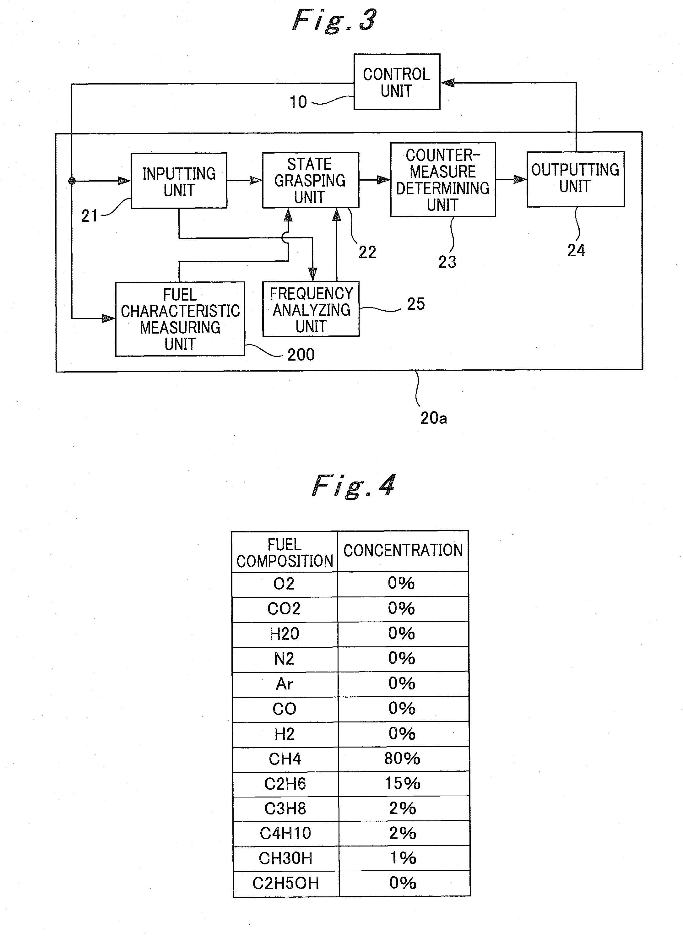
[0107]A first embodiment of the present invention will be described with reference to the accompanying drawings. FIG. 3 is a block diagram showing an internal configuration of an automatic adjusting unit used in a gas turbine system of this embodiment.

[0108]An automatic adjusting unit 20a (corresponding to the automatic adjusting unit 20 in FIG. 1) shown in FIG. 3 includes an inputting unit 21 to which measurement results at respective units of the gas turbine 2 are inputted, a state grasping unit 22 for grasping a state of the gas turbine 2, a countermeasure determining unit 23 for setting up adjustment amounts of the respective units of the gas turbine 2 on the basis of the state of the gas turbine 2 confirmed by the state grasping unit 22, an outputting unit 24 for outputting the adjustment amounts set up by the countermeasure determining unit 23 to the controller 10 (see FIG. 1), and a frequency analyzing unit 25 for analyzing the pressure fluctuation and the acceleration of the...

second embodiment

[0141]A second embodiment of the present invention will be described with reference to the accompanying drawings. FIG. 13 is a block diagram showing an internal configuration of an automatic adjusting unit used in a gas turbine system of this embodiment. In the configuration of the automatic adjusting unit in FIG. 13, constituents used for the same purposes as the configuration of the automatic adjusting unit in FIG. 3 will be designated by the same reference numerals and detailed description thereof will be omitted.

[0142]Unlike the automatic adjusting unit 20a shown in FIG. 3, an automatic adjusting unit 20b shown in FIG. 13 (which corresponds to the automatic adjusting unit 20 in FIG. 1) includes a fuel characteristic estimating unit 201 for estimating the fuel composition by use of the process amounts to be inputted from the process amount measuring unit 4 of the gas turbine 2 through the inputting unit 21 instead of installing the fuel characteristic measuring unit 200 in the ga...

third embodiment

[0148]A third embodiment of the present invention will be described with reference to the accompanying drawings. FIG. 15 is a block diagram showing an internal configuration of an automatic adjusting unit used in a gas turbine system of this embodiment. In the configuration of the automatic adjusting unit in FIG. 15, constituents used for the same purposes as the configuration of the automatic adjusting unit in FIG. 3 will be designated by the same reference numerals and detailed description thereof will be omitted.

[0149]An automatic adjusting unit 20c shown in FIG. 15 (which corresponds to the automatic adjusting unit 20 in FIG. 1) has a configuration obtained by adding a combustion characteristic grasping unit 28 for constructing a mathematical model, which is formed by modeling combustion characteristics based on results of the analyses of the combustion oscillation for the respective frequency bands accumulated in the data table for state check stored in the state grasping unit ...


PUM


Abstract

An object of the present invention is to provide a gas turbine control device which is capable of performing correction on the basis of a fuel composition of fuel gas to be supplied to a gas turbine, and is capable of changing an amount of correction in response to variation with time of the gas turbine. To attain this, a frequency analyzing unit 25 performs a frequency analysis of combustion oscillation of a combustor and splits a result of the analysis into respective frequency bands. Then, a state grasping unit 22 checks an operating state of the gas turbine on the basis of the result of the analysis of the combustion oscillation and process value of the gas turbine, and corrects the checked operating state on the basis of a fuel composition or a heat capacity of fuel gas measured by a fuel characteristic measuring unit 200. A countermeasure determining unit 23 conducts a countermeasure for controlling an operating action of the gas turbine on the basis of the operating state thus checked.

Description

TECHNICAL FIELD[0001]The present invention relates to a control device for a gas turbine for performing control to suppress combustion oscillation and a system including the same.BACKGROUND ART[0002]A conventional gas turbine is configured to predetermine an air flow rate and a fuel flow rate to be sent to a combustor on the basis of a power generator output, an ambient temperature, humidity, and the like, and to perform operation based on the determined flow rate values. However, there is a possibility that fuel composition, the fuel flow rate, and the air flow rate in practice are deviated from those at the time of planning or at the time of test run adjustment due to variation in the composition or the heat capacity of the fuel gas to be supplied to the gas turbine or to secular changes such as deterioration in performance of a compressor or filter clogging, for example. Attributed to such deviation, there arises a risk of deterioration in combustion stability and eventual occurr...

Claims


Application Information

Patent Timeline
Patent Type & Authority Applications(United States)
IPC IPC(8): F02C9/00
CPCF02C3/22F02C9/00F23R2900/00013F05D2270/083F02C9/28
Inventor NOMURA, MASUMITOYAMA, KOZOIBA, HIROYUKI
Owner MITSUBISHI POWER LTD
Why Eureka
Try Eureka