
Process for producing a low density acoustical panel with improved sound absorption

Active Publication Date: 2009-05-21
USG INTERIORS LLC
View PDF18 Cites 17 Cited by
  • Summary
  • Abstract
  • Description
  • Claims
  • Application Information

AI Technical Summary

Benefits of technology

[0017]The present invention provides a process of making an acoustical ceiling panel with an open structure and improved acoustical absorption properties comprising;
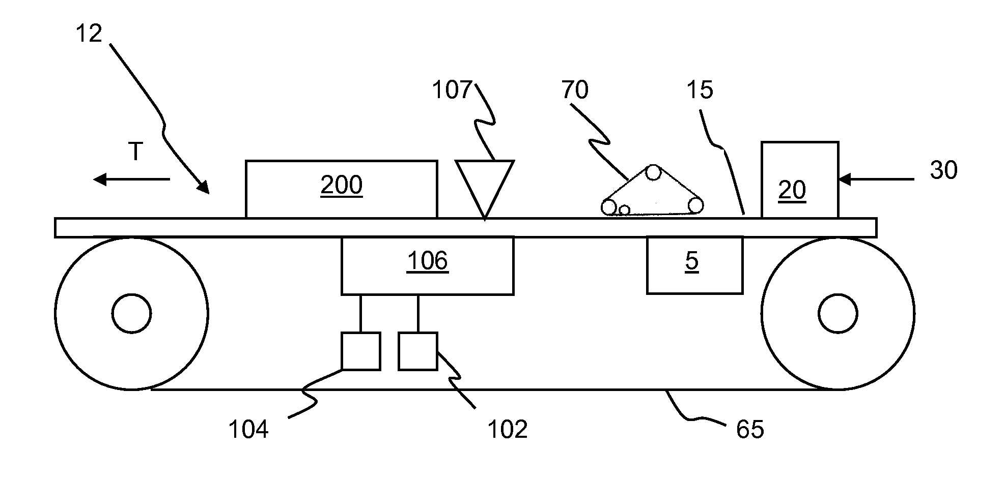
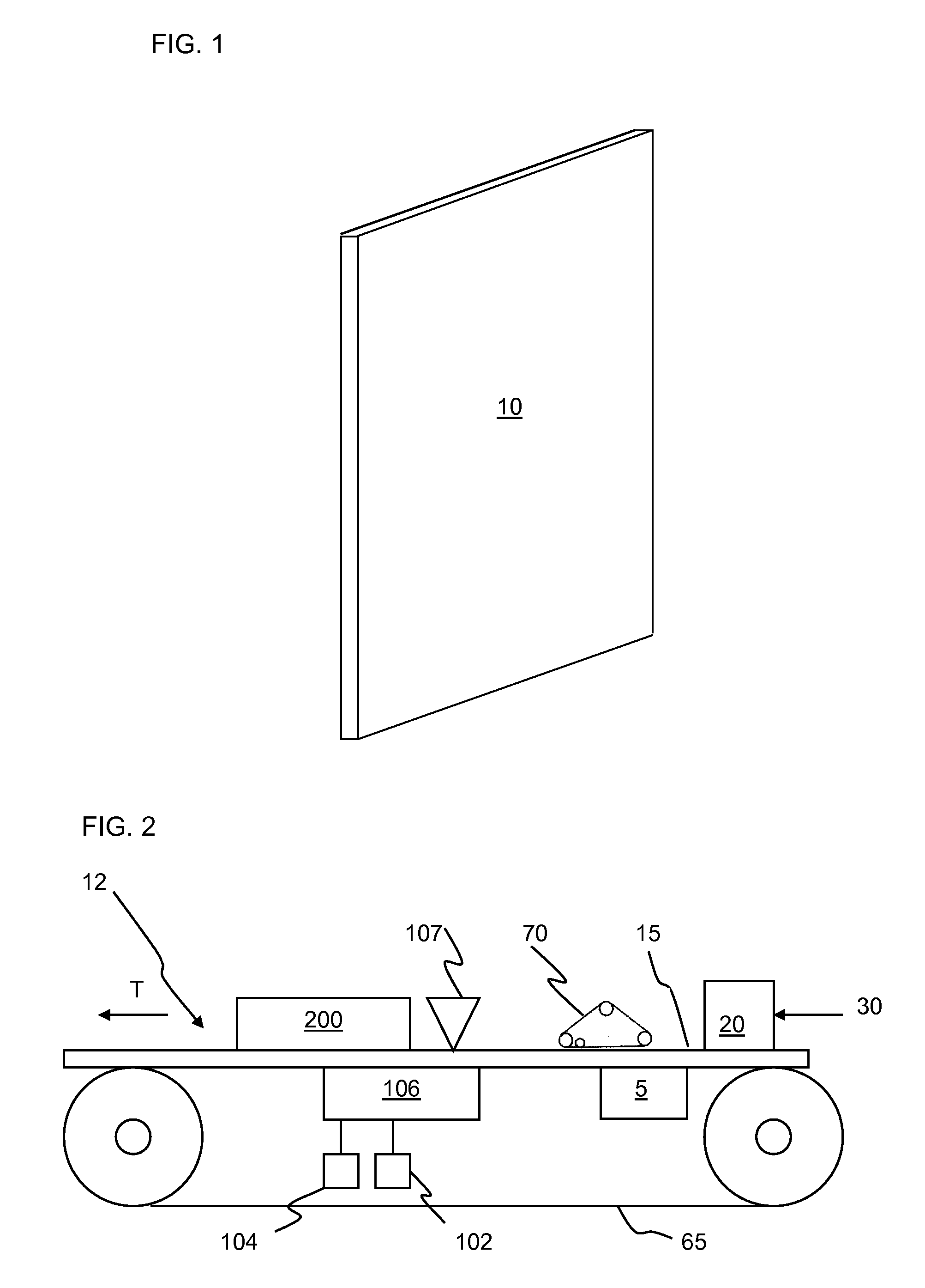
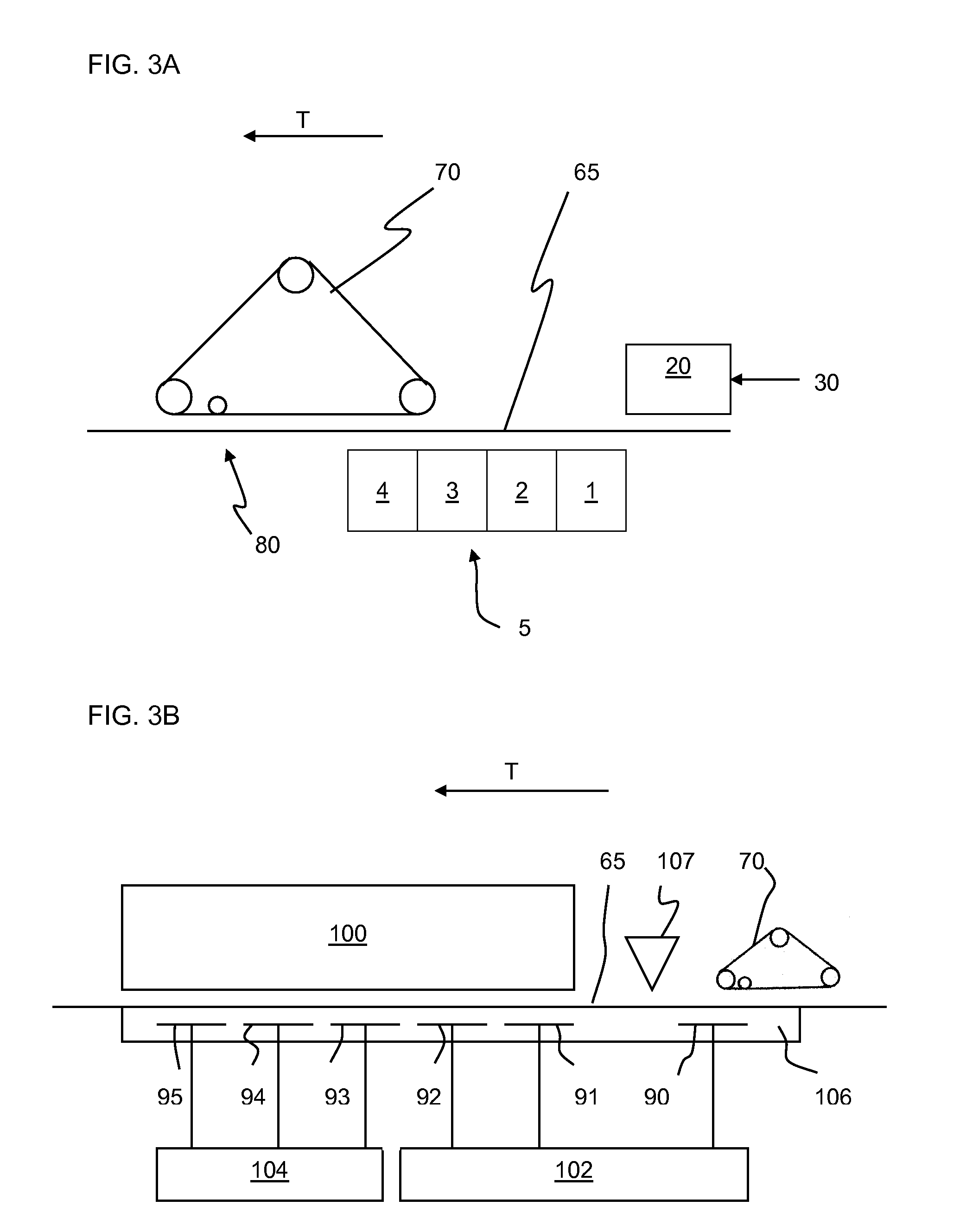
[0025]The present inventors have found a lower density, higher NRC mineral wool acoustical mat or panel product can be obtained by controlling vacuum applied during the vacuum drainage and drying steps on the wet end portion of a production line to minimize the compaction of the formed base mat. In a preferred embodiment, the wet-end operates by (1) adjusting the settings on gravity drainage boxes to allow for as much water drainage as possible from the base mat; (2) raising the level of a top wire former so there is minimal pressing of the base mat; and (3) adjusting the settings of vacuum boxes to allow for the gradual application of vacuum to the base mat.
[0027]The process of the present invention produces a lower density high mineral wool acoustical ceiling product with improved acoustical absorption properties comparable to higher end fiberglass products.
[0028]The present invention, by maximizing gravity drainage, raising the press position of the top wire former, eliminating dust and broke and gradually introducing vacuum, can achieve a free-formed product with 11-12 pounds per cubic foot (pcf) (176-192 kg / cu. meter) wet-end density with a NRC at or above 0.85. The nominal 12 pcf density is maintained at a trimmer despite the static pressure exerted by the downstream vacuum boxes and the application of flow-through drying.
[0030]The present invention can also obtain a nominal 0.900 inch (2.29 cm) product with an NRC of 0.80 by using standard wet end set-up but with gradually increasing vacuum setting to aid production of a lower density base mat.

Problems solved by technology

Under some circumstances NRC's greater than 1 may be obtained, but this is an artifact of the test method due to diffraction / edge to area effects.

Method used


Image

  • Process for producing a low density acoustical panel with improved sound absorption
  • Process for producing a low density acoustical panel with improved sound absorption
  • Process for producing a low density acoustical panel with improved sound absorption

Examples


example 1

[0105]This example employed a target mixture comprising about 93 wt. %, mineral wool, about 4.7 wt. %, thermoplastic binders and about 2.0 wt. %, starch on a dry ingredient basis.

[0106]The panels were made as described above in the section entitled “Making a Panel of the Present Invention”.

[0107]The Gravity Drainage Box Settings (see FIG. 3A) and Vacuum Box Settings (see FIG. 3B) for the Hi-NRC acoustical boards of the present invention are compared to the current commercial MARS® acoustical board, which has an NRC of 0.70, in TABLES 2 and 3. The gravity drainage boxes are labeled 1, 2, 3 and 4 as in FIG. 3A. The vacuum boxes are labeled 90, 91, 92, 93, 94 and 95 as in FIG. 3B.

TABLE 2Gravity Drainage Box SettingsBase matBase matThicknessDensityGravityGravityGravityGravityProduct(in.)(lbs / ft3)NRCBox 1Box 2Box 3Box 4Standard0.81015.00.70closedclosed½ openopen1MARS ®acousticalboardHi-NRC0.90014.50.80closedclosed½ openopen1acousticalboard #1Hi-NRC1.05012.50.90closedclosedopenopen1acoust...

example 2

Preparation of Plant Scale Boards

[0113]The press was raised to the maximum position, gravity drainage was maximized, and vacuum in the press box was varied while other vacuum settings were left in their conventional position. Thus, the trial conditions for this data included a raised top wire former 70 (hereinafter also referred to as a “press”) raised to a maximum position, maximized gravity drainage and variable vacuum settings on the AP vacuum box with the other vacuum settings the same as the standard MARS® acoustical board product. Any dust and broke has been removed. Note that the wet end sample is taken immediately after the AP vacuum box. TABLE 4 shows the resulting data.

TABLE 4PressVacuumMoistureBoxThicknessWeightDensityContentBoard #(in Hg)(in)(lbs)(lbs / ft3)(%)ENRC1A0.001.18641.2111.0884.20.8901B0.001.17240.0510.9084.20.8902A0.501.04938.3011.6481.40.8752B0.501.04239.4612.0881.40.8753A1.000.95835.2811.7473.80.8343B1.000.98736.6911.8573.80.8344A1.400.98436.8211.9370.70.8364B...

example 3

Preparation of Plant Scale Boards

[0117]The trial data of TABLE 5 demonstrates that simply raising the press has a minimal effect on thickness, density, and ENRC. The only difference between these two sets of data (“control” and “No Press”) was that the top wire former 70 was raised to its maximum position for the samples labeled “No Press”. The samples were taken at the trimmer and no wet end samples were taken. The press was raised to the maximum position from (from 0.780 inches to 1.187 inches). The gravity box settings were left in the standard positions.

TABLE 5Press VacuumThicknessWeightDensityBoard #Box (inches Hg)(in)(lbs)(lbs / ft3)ENRCControl #11.860.82638.4514.840.704Control #21.860.81538.9415.240.700No Press #11.860.84737.6114.160.730No Press #21.860.81836.8314.360.729No Press #31.860.85137.0713.890.707

[0118]Simply raising the press (in the absence of also increasing gravity drainage and reducing vacuum settings produced only a small reduction in base mat density and only a ...


PUM

PropertyMeasurementUnit
Fractionaaaaaaaaaa
Fractionaaaaaaaaaa
Fractionaaaaaaaaaa

Abstract

A process useful for producing low density high mineral wool based acoustical panels with improved acoustical absorption properties using a water felting process is disclosed. The process includes forming a dilute slurry mixture including water, mineral wool, a thermoplastic binder and / or starch; and distributing the dilute slurry on a porous carrier to have the slurry dewatered to a base mat by gravity drainage to remove water by gravity. A vacuum is adjusted to gradually apply vacuum to the gravity dewatered base mat to further dewater the base mat without subjecting the mat to static pressure that would compress the base mat. The base mat is dried to form an acoustical ceiling product that has a low density and excellent acoustical absorption properties.

Description

FIELD OF THE INVENTION[0001]This invention relates to a process for preparing low density high mineral wool acoustical tiles and panels for ceiling and other applications with improved sound absorption. More particularly, the invention relates to an acoustical panel composition made using an improved water felting process for achieving a lower density high mineral wool acoustical ceiling product with higher NRC values than acoustical panels made using the conventional water felting process.BACKGROUND OF THE INVENTION[0002]The water felting of dilute aqueous dispersions of mineral wool and lightweight aggregate is a well known commercial process for manufacturing acoustical ceiling tile or panels. In this process, aqueous slurry of mineral wool, lightweight aggregate, cellulose fiber, binder and other desired ingredients is flowed onto a moving foraminous support wire, such as that of a Fourdinier or Oliver mat forming machine, for dewatering. The slurry may be first dewatered by gra...

Claims


Application Information

Patent Timeline
IPC IPC(8): D21H11/20
CPCD21H11/20D21H13/40E04B9/001E04B1/86D21J1/20C04B26/28C04B2111/00612C04B2111/52C03C25/30C03C25/321Y02W30/91C04B14/185C04B14/46C04B18/241C04B24/38C04B40/00
Inventor ENGLERT, MARK H.YU, QING
Owner USG INTERIORS LLC
Learn More