Extreme ultraviolet light source device and a method for generating extreme ultraviolet radiation

a light source device and ultraviolet radiation technology, applied in the direction of optical radiation measurement, instruments, therapy, etc., can solve the problems of not being able to generate ultraviolet radiation in the discharge channel, and not being able to actively control the spatial density distribution

Inactive Publication Date: 2009-05-21
USHIO DENKI KK +1
View PDF10 Cites 30 Cited by
  • Summary
  • Abstract
  • Description
  • Claims
  • Application Information

AI Technical Summary

Benefits of technology

[0022]The present invention was achieved in view of the aforementioned circumstances. The object of the present invention is to provide an EUV light source device that allows the position of a discharge channel to be defined and proper setting of the density of high temperature plasma raw material (gas) in the discharge channel and a method of generating EUV.

Problems solved by technology

However, the following problems arise in the constitution of a device such as shown in JP-A-2005-522839 and corresponding U.S. Pat. No. 6,972,421 B2.
It is not possible, however, to actively control the spatial density distribution of the high temperature plasma raw material (gas) distribution in the discharge channel, and so the high temperature plasma raw material (gas) spatial density distribution that is optimal for EUV emission will not necessarily be available in the discharge channel.

Method used


Image

  • Extreme ultraviolet light source device and a method for generating extreme ultraviolet radiation
  • Extreme ultraviolet light source device and a method for generating extreme ultraviolet radiation
  • Extreme ultraviolet light source device and a method for generating extreme ultraviolet radiation

Examples


first embodiment

[0113]FIGS. 4 & 5 show the configuration (a sectional view) of the extreme ultraviolet (EUV) light source device according to the present invention. FIG. 4 is a front view of the EUV light source device according to the present invention. EUV radiation is extracted from the left side in the drawing. FIG. 5 is a top view of the EUV light source device according to the present invention.

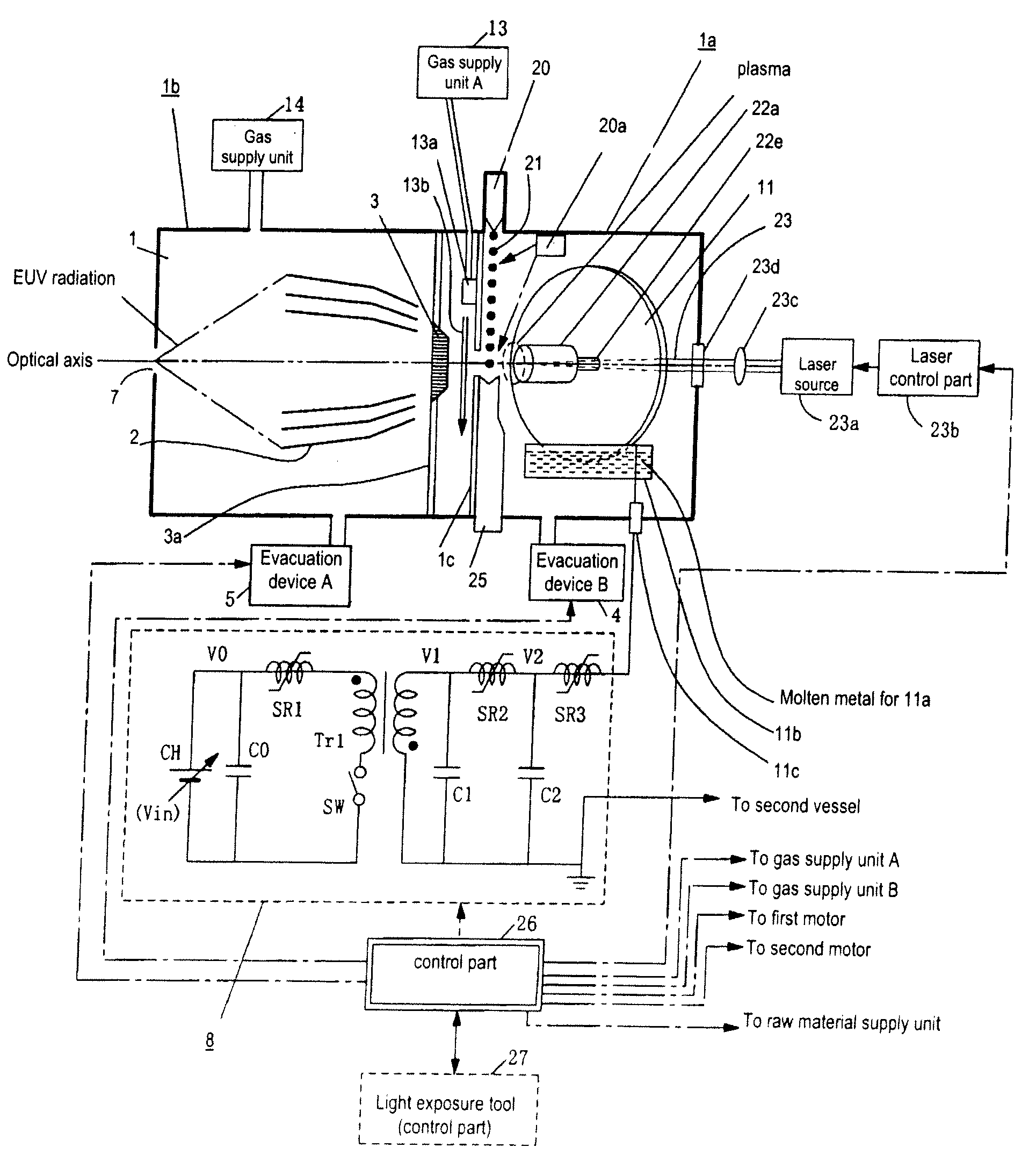
[0114]The EUV light source device in FIGS. 4 & 5 has a chamber 1, which is a discharge vessel. The chamber 1 is essentially divided into two spaces by a barrier 1c having an opening. In one space a discharge part is located. The discharge part is a heating and excitation means for heating and exciting a high temperature plasma raw material containing an EUV radiating species. The discharge part comprises a pair of electrodes 11, 12.

[0115]On the other space are provided EUV radiation collector optics 2 for collecting EUV radiation emitted from the high temperature plasma, which was generated by heating ...

first alternative embodiment

(1) First Alternative Embodiment

[0281]FIGS. 10 & 11 are views explaining the first alternative of the present embodiment. More specifically, FIG. 10 is a front view of the EUV light source device according to the present invention. EUV radiation is extracted on the left side in the drawing. In FIG. 10, the raw material supply unit is replaced for one in the EUV light source device in FIG. 4. FIG. 10 mainly shows the arrangement and configuration of the raw material supply unit and omits part of the EUV light source device so as to make the understanding easier. The omitted part is the same as in FIG. 4.

[0282]FIG. 11 is a top view of the EUV light source device according to the present invention. Like FIG. 10, part of the EUV light source device is omitted.

[0283]In the alternative embodiment as shown in FIGS. 10 & 11, linear raw material 31 is used as the high temperature plasma raw material. Specifically, it is a metal wire containing an extreme ultraviolet radiating species such as...

second alternative embodiment

(2) Second Alternative Embodiment

[0293]FIGS. 12-14 are views explaining the second alternative of the present embodiment. More specifically, FIG. 12 is a front view of the EUV light source device according to the present invention. EUV radiation is extracted on the left side in the drawing. In FIG. 12, the raw material supply unit 20 of the EUV light source device shown in FIG. 4 is replaced.

[0294]FIG. 12 mainly shows the arrangement and configuration of the raw material supply unit and omits part of the EUV light source device so as to make the understanding easier. The omitted part is the same as one in FIG. 4.

[0295]FIG. 13 is a top view of the EUV light source device according to the present invention. FIG. 14 is a side view of the EUV light source device according to the present invention. Like FIG. 12, part of the EUV light source device is omitted.

[0296]In the second alternative embodiment as shown in FIGS. 12-14, liquid raw material is used as high temperature plasma raw mate...


PUM


Abstract

High temperature plasma raw material is added drop-wise, for example, and evaporated by irradiation with a laser beam. The laser beam passes through a discharge area between a pair of electrodes and irradiates the high temperature plasma raw material. Pulsed power is applied to the space between the electrodes in such a way that discharge current reaches a specified threshold value at a time when at least part of the evaporated material reaches the discharge channel. As a result, discharge starts between the electrodes, plasma is heated and excited and then EUV radiation is generated. The EUV radiation thus generated passes through a foil trap, is collected by EUV radiation collector optics and then extracted. The irradiation of the laser beam allows setting of the space density of the high temperature plasma raw material to a specified distribution and defining of the position of a discharge channel.

Description

BACKGROUND OF THE INVENTION[0001]1. Field of Invention[0002]The present invention relates to an extreme ultraviolet light source device for generating extreme ultraviolet radiation from plasma generated by electric discharge and a method of generating extreme ultraviolet radiation Especially, the present invention relates to an extreme ultraviolet light source device and a method of generating extreme ultraviolet radiation which generates extreme ultraviolet radiation using plasma generated by discharge following gasification of a high temperature plasma raw material by energy beam irradiation of a high temperature plasma raw material for generation of extreme ultraviolet radiation that is supplied to the vicinity of the discharge electrodes.[0003]2. Description of Related Art[0004]With the micro-miniaturization and higher integration of semiconductor integrated circuits, there are demands for improved resolution in projection lithography devices used in manufacturing integrated cir...

Claims


Application Information

Patent Timeline
Patent Type & Authority Applications(United States)
IPC IPC(8): G01J3/10
CPCB82Y10/00H05G2/003G03F7/70033
Inventor HOSOKAI, TOMONAOHORIOKA, KAZUHIKOSEKI, KYOHEIMIZOKOSHI, HIROSHI
Owner USHIO DENKI KK
Why Eureka
Try Eureka