Green Electroluminescent Compounds and Organic Electroluminescent Device Using the Same

a technology of green electroluminescent materials and organic electroluminescent devices, which is applied in the direction of discharge tube luminescnet screens, perylene derivatives, anthracene dyes, etc., can solve the problems of insufficient enhancement of the lifespan of green materials, insufficient green electroluminescent materials having long life, and insufficient green electroluminescent materials. achieve the effect of high efficiency, high efficiency and high efficiency

Inactive Publication Date: 2009-05-21
HYUN SEUNG HAK +10
View PDF4 Cites 21 Cited by
  • Summary
  • Abstract
  • Description
  • Claims
  • Application Information

AI Technical Summary

Benefits of technology

[0018]The compounds of Chemical Formula 1 or 2 according to the present invention are characterized by the structure of novel concept with maximized electroluminescent efficiency in green light-emitting diode and lifetime of device which were not expectable with conventional inventions.
[0019]The compounds of Chemical Formula 1 or 2 according to the invention adopted a structure showing an efficient energy transfer mechanism between the host and the dopant, which can reveal electroluminescent property with a reliably high efficiency on the basis of improvement in electron density distribution. The structure of the novel compounds according to the present invention can provide a skeletal which can also tune an electroluminescent property with high efficiency in the range from blue to red, not only for green light. Beyond the concept of using a host material with high electric conductivity such as Alq, the invention applies a host having appropriate balance of hole conductivity and electron conductivity, thereby overcoming the problems of conventional materials including low initial efficiency and short lifetime, and ensures the electroluminescent property with high performance having high efficiency and long life for each color.
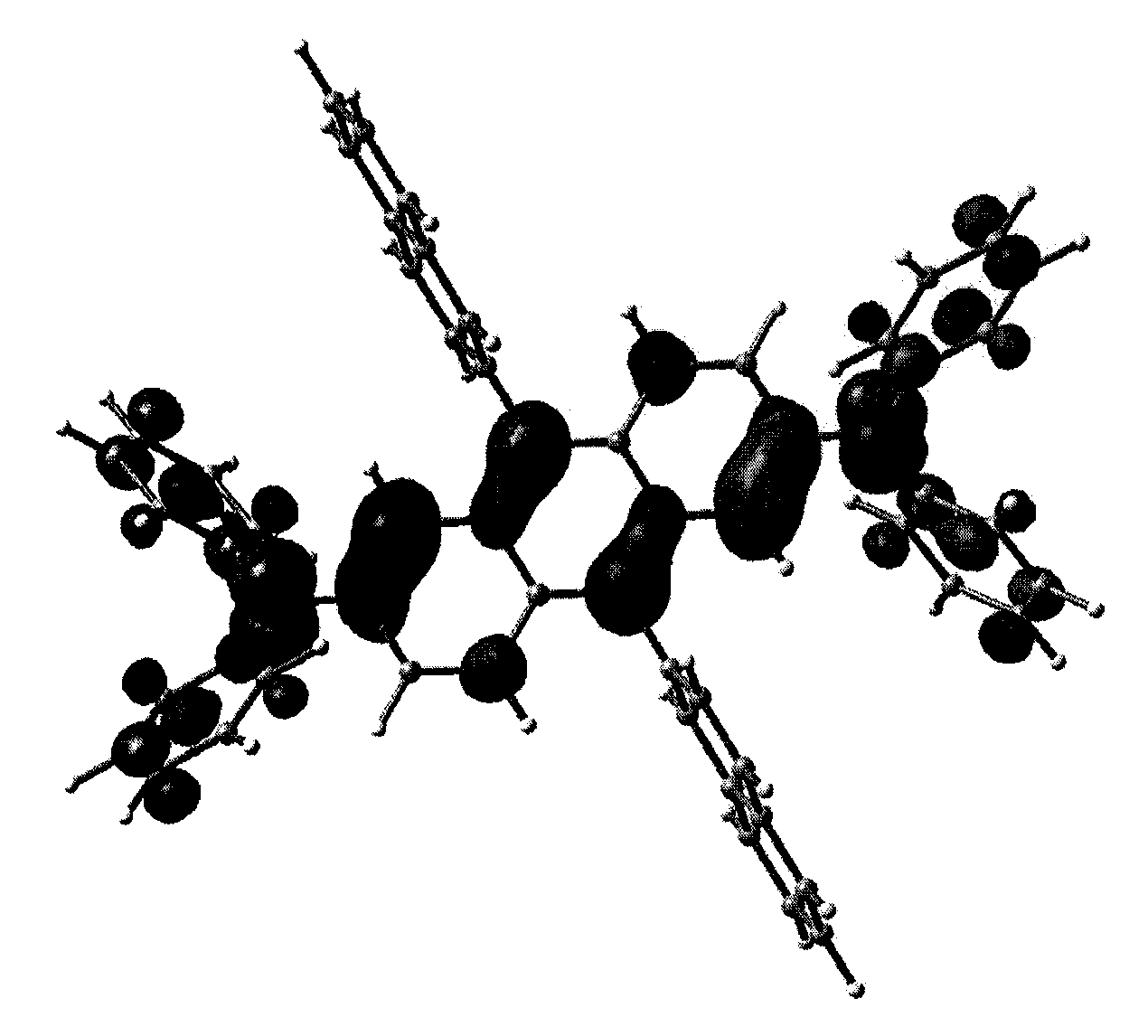
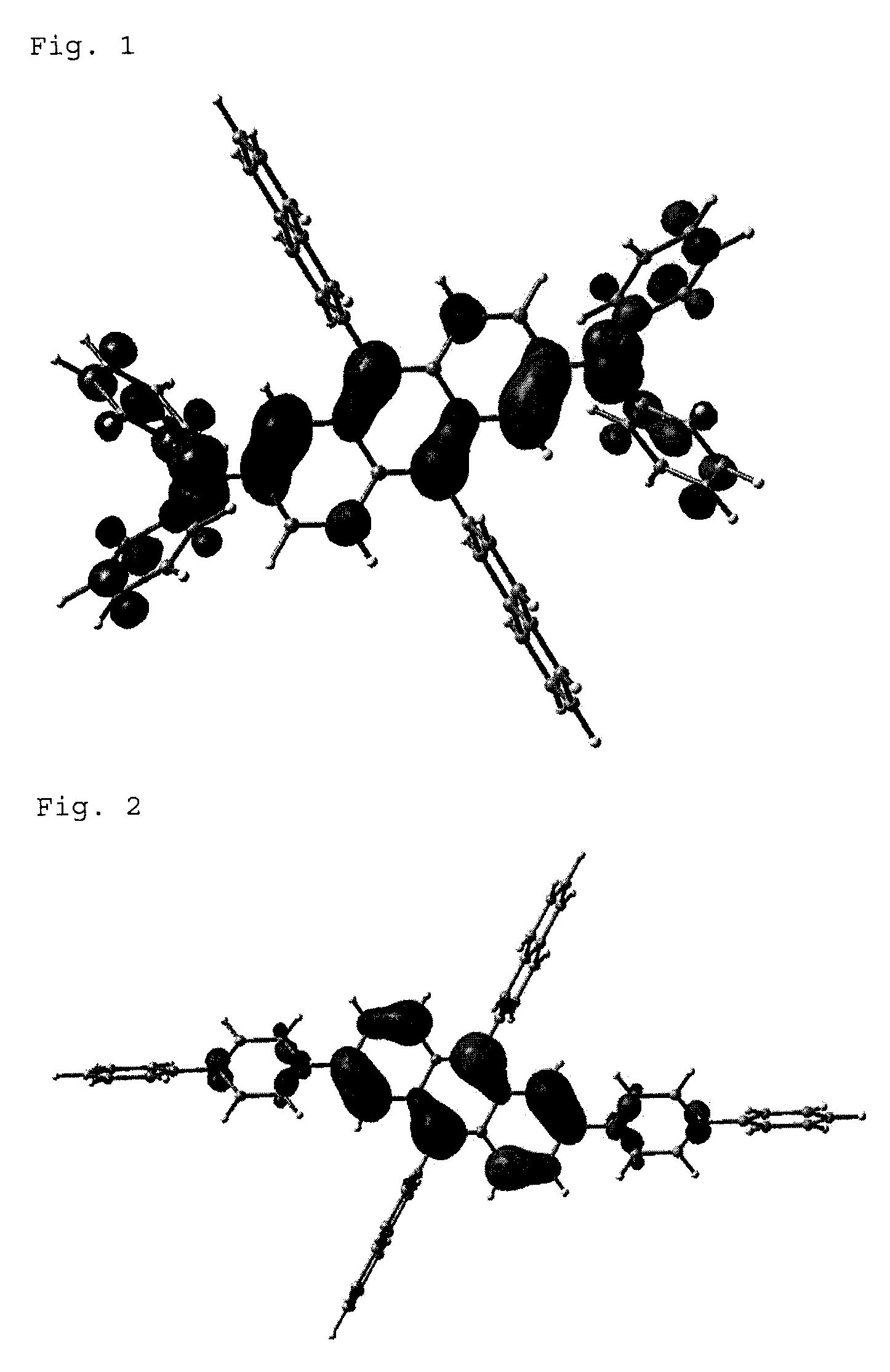
[0020]As can be seen from FIG. 1 and FIG. 2 showing the electron density distribution of the compound according to the invention wherein amine groups are incorporated to 2- and 6-position of anthracene and 2-naphthyl group as a fused multi-cyclic aromatic group are substituted at 9- and 10-position, and the electron density distribution of the compound wherein aromatic rings are incorporated to 2- and 6-position of anthracene, respectively, when an amine group is substituted at i-position (2- and 6- or 7-position) of anthracene, electroluminescent property with high efficiency is obtained due to even electron distribution up to the side branch of core skeletal; while when an aromatic ring is directly positioned on the core skeletal, the electron density of the side branch noticeably falls down. This illustrates that amine groups should be directly incorporated to the core skeletal in order to get electroluminescent property with high efficiency.
[0021]These results show that the electroluminescent material according to the prior art, in which an aromatic ring is employed as a spacer only for the purpose of tuning the light-emitting wavelength, inevitably has the limitation in improving the electroluminescent efficiency.

Problems solved by technology

However, conventional green electroluminescent materials still have many problems to achieve manufacturing panels of large scale with low power consumption.
Though they show from 2 to 5 times of electroluminescent property as compared to red or blue electroluminescent materials, development of green electroluminescent material become a burden with the improvement of properties of red or blue electroluminescent material.
In the meanwhile, enhancement of lifespan of the green material is still insufficient, so that a green electroluminescent material having long life is seriously required.
However, the above-suggested compound has problems of low hole transport property and insufficient luminance, though the electroluminescent efficiency has been increased.
Those materials are not employed as electroluminescent material with limitation to be applied as practical electroluminescent material, because Compound I emits light of light-blue color with low electroluminescent efficiency.
Though the compounds suggested by Japanese Patent Laid-Open No. 2004-91334, applied as a hole transport layer, could lower the ionization potential and enhance the hole transport property due to many amine functional groups, they have problem of short lifetime of operation as a hole transport layer because of multiple amine functional groups.
However, U.S. Pat. No. 6,465,115 did not employed Compound K and Compound L in the luminescent region, and could not confirm the properties of those materials in the luminescent region.

Method used


Image

  • Green Electroluminescent Compounds and Organic Electroluminescent Device Using the Same
  • Green Electroluminescent Compounds and Organic Electroluminescent Device Using the Same
  • Green Electroluminescent Compounds and Organic Electroluminescent Device Using the Same

Examples


preparation example 1

Preparation of Compound (1) (Chemical Formula 1: R1=R2=2-naphthayl, R3=R4=R5=R6=phenyl)

[0049]In dry toluene, dissolved were 2,6-dichloroanthraquinone (1.0 g, 3.6 mmol) and diphenylamine (1.3 g, 7.7 mmol), and palladium acetate (Pd(OAc)2)(2.4 g, 24.4 mmol), tri(t-butyl) phosphine (P(t-Bu)3) (0.2 mL, 1.9 mmol) and sodium t-butoxide (t-BuONa) (0.93 g, 9.7 mmol) were added thereto. The resultant mixture was heated under reflux at 110° C. for 3 days. When the reaction was completed, 10 mL of distilled water was added, and the mixture was stirred for 30 minutes. The solid generated was filtered, washed with solvent such as acetone and THF, dried and recrystallized from methylene chloride to give bis(2,6-diphenylamino)anthraquinone (1.1 g, 2.0 mmol, yield: 56%).

[0050]Diethyl ether solution (5 mL) of 2-naphthyllithium which had been previously prepared by using diphenylamine (0.74 g, 4.4 mmol) and n-buthyllithium (n-BuLi) (1.8 mL, 4.5 mmol, 2.5 M in hexane) was slowly added to a solution of...

preparation example 2

Preparation of Compound (2) (Chemical Formula 1: R1=R2=R3=R5=2-naphthayl, R4=R6=phenyl)

[0054]The same procedure as described in Preparation Example 1 was repeated but using N-phenyl-2-naphthylamine (1.7 g, 7.8 mmol) to obtain Compound (2) (0.53 g, 0.61 mmol, overall yield: 17%).

[0055]1H NMR (200 MHz, CDCl3): δ 6.45 (d, 4H), 6.6 (t, 2H), 6.75-6.8 (m, 8H), 7.0-7.15 (m, 6H), 7.2-7.3 (m, 6H), 7.45-7.6 (m, 10H), 7.65-7.8 (m, 6H), 7.9 (s, 2H)

[0056]MS / FAB: 864 (found), 865.10 (calculated)

preparation example 3

Preparation of Compound (3) (Chemical Formula 1: R1=R2=2-naphthyl, R3=R5=1-naphthyl, R4=R6=phenyl)

[0057]The same procedure as described in Preparation Example 1 was repeated but using N-phenyl-1-naphthylamine (1.7 g, 7.8 mmol) to obtain Compound (3) (0.41 g, 0.47 mmol, overall yield: 13%).

[0058]1H NMR (200 MHz, CDCl3): δ 6.45 (d, 4H), 6.5 (d, 2H), 6.6 (t, 2H), 6.75-6.8 (m, 4H), 7.0-7.05 (m, 4H), 7.15-7.2 (m, 4H), 7.3-7.35 (m, 8H), 7.55-7.8 (m, 14H), 7.9 (s, 2H)

[0059]MS / FAB: 864 (found), 865.10 (calculated)


PUM

PropertyMeasurementUnit
thicknessaaaaaaaaaa
thicknessaaaaaaaaaa
thicknessaaaaaaaaaa

Abstract

The present invention relates to organic electroluminescent compounds represented by Chemical Formula 1 or 2, a process for preparing the same, and an organic light emitting diode (OLED) which comprises, as a luminescent region interposed between an anode and a cathode, at least one compound (s) selected from those represented by Chemical Formula 1 or 2, and at least one compound selected from anthracene derivatives, benz[a]anthracene derivatives and naphthacene derivatives. The electroluminescent compound according to the present invention is a green electroluminescent compound having maximized electroluminescent efficiency and lifetime of device.

Description

FIELD OF THE INVENTION[0001]The present invention relates to organic electroluminescent compounds represented by Chemical Formula 1 or 2, a process for preparing the same, and an organic light emitting diode (OLED) which comprises, as a luminescent region interposed between an anode and a cathode, at least one compound(s) selected from those represented by Chemical Formula 1 or 2, and at least one compound selected from anthracene derivatives, benz[a]anthracene derivatives and naphthacene derivatives.BACKGROUND OF THE RELATED ART[0002]The most important matter in developing an OLED having high efficiency and long life is development of electroluminescent material of high performance. In view of current development of electroluminescent material, green electroluminescent materials show superior electroluminescent property to red or blue electroluminescent materials. However, conventional green electroluminescent materials still have many problems to achieve manufacturing panels of la...

Claims


Application Information

Patent Timeline
Patent Type & Authority Applications(United States)
IPC IPC(8): C07C211/61H01J1/63
CPCC07C211/61C09B3/14C07C2103/18C07C2103/24C07C2103/40C07C2103/50C09K11/06C09K2211/1007C09K2211/1011C09K2211/1014H01L51/0052H01L51/006H01L51/0081H01L51/5012H05B33/14C09B57/001C09B57/008C09B1/00C09B1/32C09B3/02C07C217/92C07C2603/18C07C2603/24C07C2603/40C07C2603/50H10K85/633H10K85/615H10K85/324H10K50/11
Inventor HYUN, SEUNG-HAKLEE, JEA-SUNGSI, SANG-MANHAN, KEUN-HEEKWON, HYUCK-JOOCHO, YOUNG-JUNYOON, SEUNG-SOOKIM, BONG-OKKIM, SUNG-MINKIM, CHI-SIKCHOI, IL-WON
Owner HYUN SEUNG HAK
Why Eureka
Try Eureka