Hydrodynamic bearing device, and spindle motor and information apparatus equipped with same

a technology of bearing device and bearing shaft, which is applied in the direction of bearings, shafts and bearings, rotary bearings, etc., can solve the problems of lubricant seeping into the places of insufficient adhesive strength, affecting the adhesion strength of the bearing, so as to achieve the effect of reducing the adhesive strength

Active Publication Date: 2009-05-21
PHC HLDG CORP
View PDF5 Cites 4 Cited by
  • Summary
  • Abstract
  • Description
  • Claims
  • Application Information

AI Technical Summary

Benefits of technology

[0032]With the present invention, good communication is obtained in the center part of the communicating path, there are no places of insufficient adhesive between bonded members, sufficient adhesive strength is maintained immediately after assembly, and from a long-term standpoint of subjecting the product to a heat

Problems solved by technology

As a result, even if a communicating path is ensured, any portions where there is not enough adhesive will already be lacking in adhesive strength at the initial assembly stage.
Furthermore, if there is not enough adhesive at portions where adhesive is supposed to be present, the lubricant may seep into this places.
If the product is subjected to a heat cycle or heat shock in this stat

Method used


Image

  • Hydrodynamic bearing device, and spindle motor and information apparatus equipped with same
  • Hydrodynamic bearing device, and spindle motor and information apparatus equipped with same
  • Hydrodynamic bearing device, and spindle motor and information apparatus equipped with same

Examples


embodiment 1

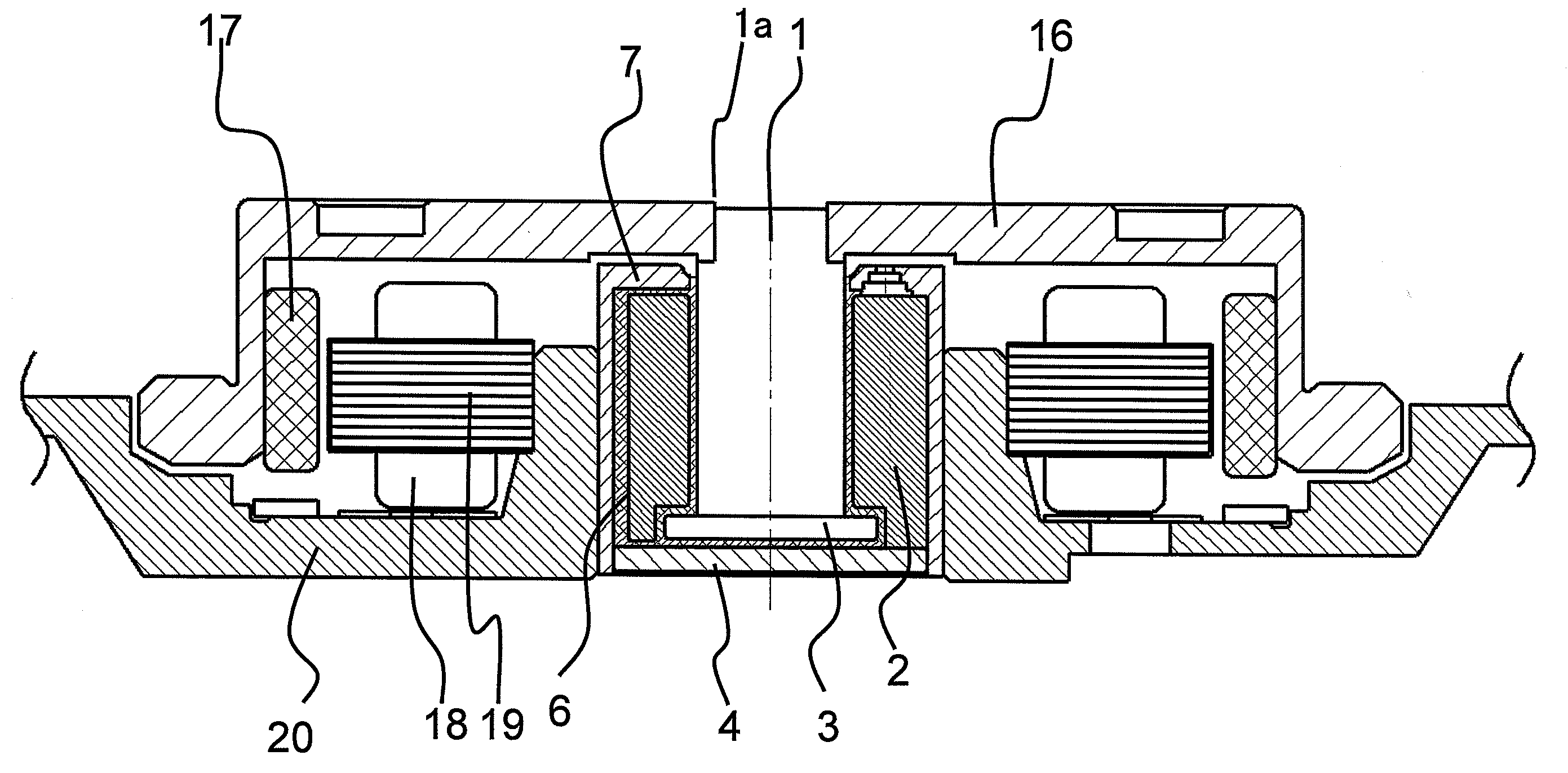
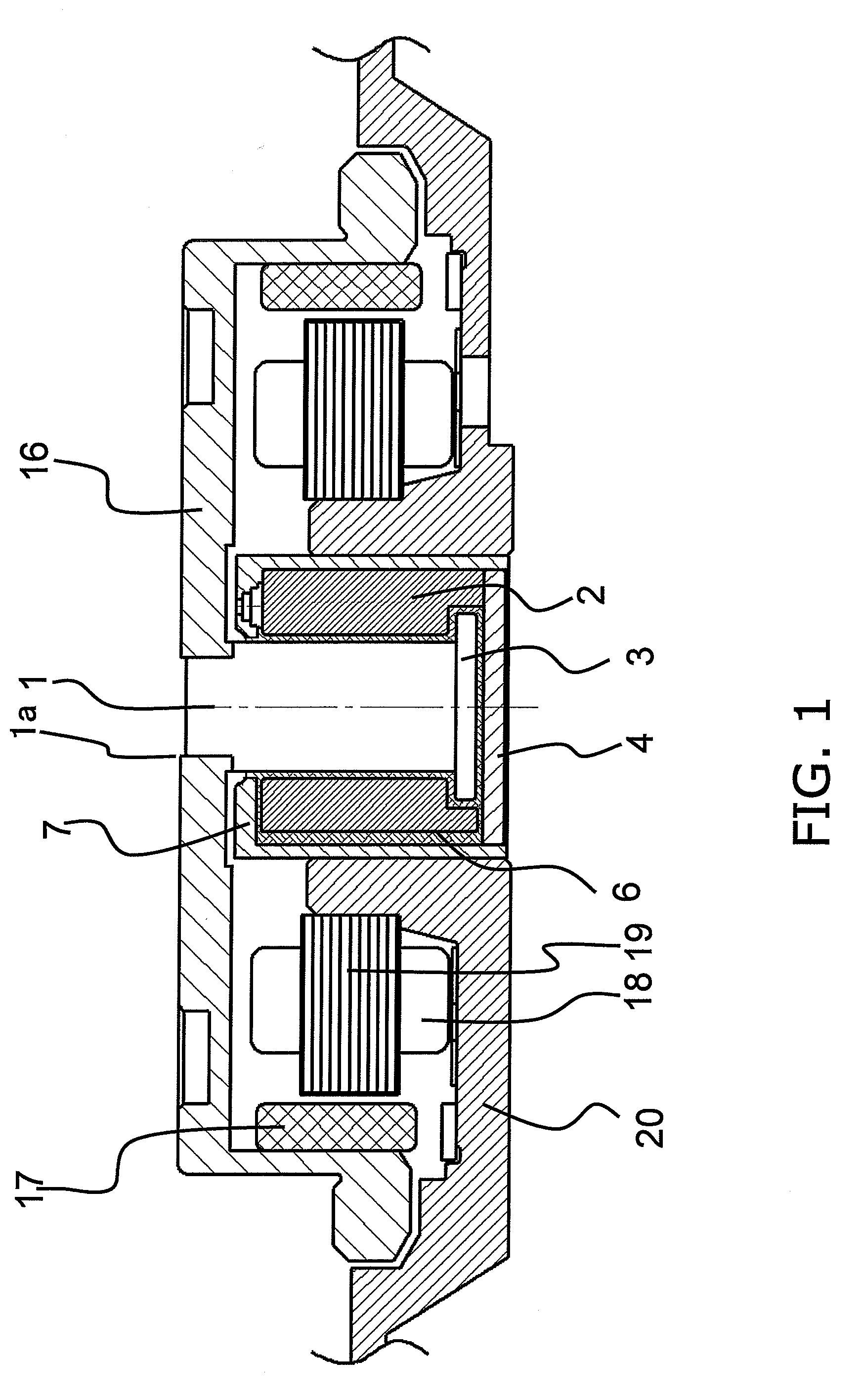
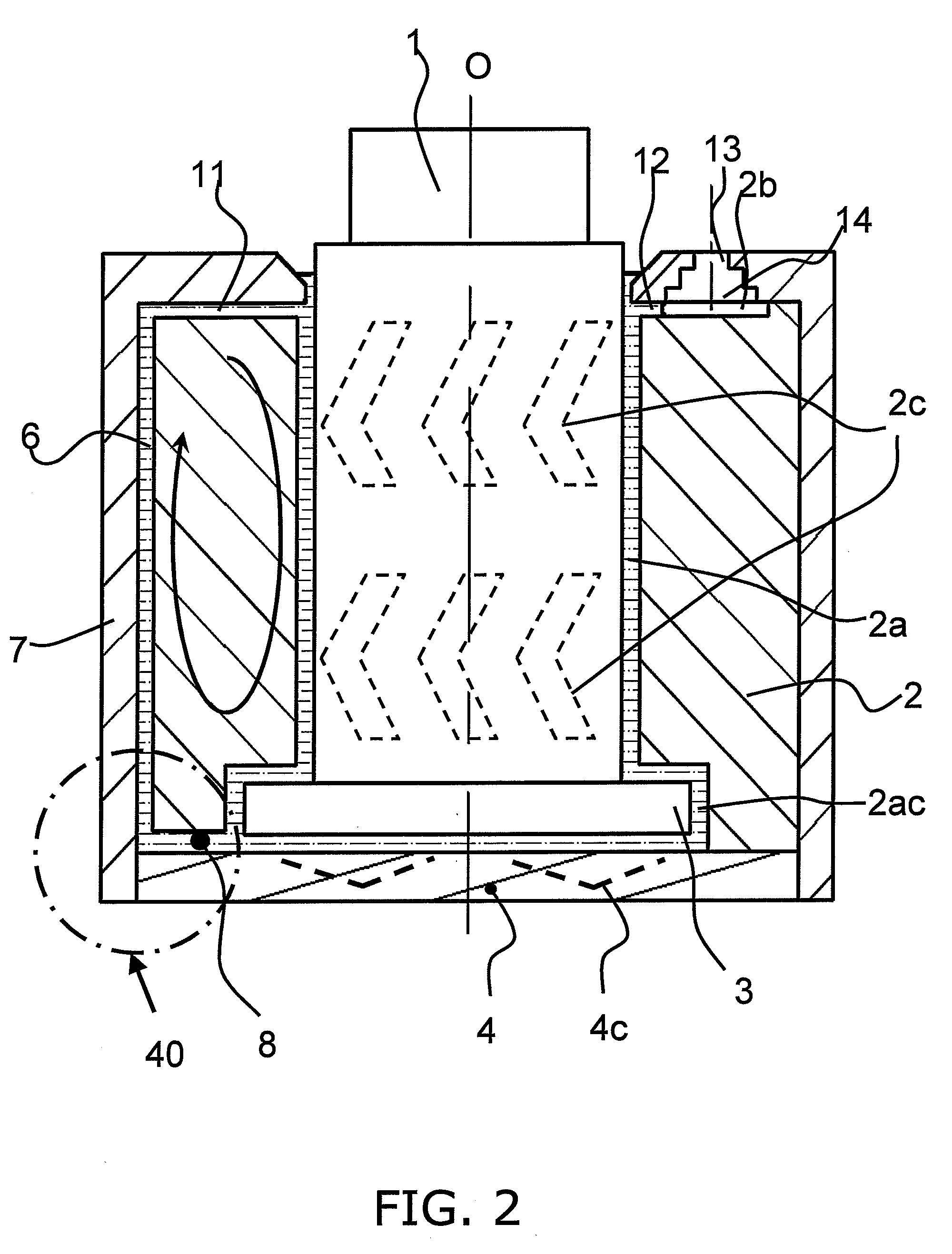
[0034]FIG. 1 is a cross section of a spindle motor for a hard disk drive equipped with the hydrodynamic bearing device of the first embodiment of the present invention. FIG. 2 is a cross section of this hydrodynamic bearing device. In the following description, for the sake of convenience, we will describe a state in which the open end of a bearing hole 2a of a sleeve 2 is disposed upward and the closed end downward, as shown in FIGS. 1 and 2, but when the device is actually being used it is not limited to this orientation.

[0035]The hydrodynamic bearing device installed in this spindle motor has a cylindrical shaft 1 inserted, in a state of being relatively rotatable via a specific gap (space), in the cylindrical sleeve 2 having the bearing hole 2a, which has a circular open end on the upper side that is open and a closed end on the lower side that is closed.

[0036]A large-diameter thrust flange 3 in the form of a disk is fixed to the lower end of the shaft 1 by being fitted and link...

embodiment 2

[0060]FIG. 6 is a cross section of the area around where the bearing device is mounted in a spindle motor equipped with the hydrodynamic bearing device pertaining to Embodiment 2 of the present invention.

[0061]Here, an outer cylinder member 30 is bonded to a shaft 51, and a radial bearing is formed in a tiny gap formed between a sleeve 92 and the outer periphery of the outer cylinder member 30. Here, a spiral axial direction communicating path 36 is formed on the outer peripheral cylinder surface of the stainless steel shaft 51. The outer cylinder member 30 is composed of zirconia, silicon carbide, alumina, or another such ceramic, and a radial direction communicating path 38 is formed at the upper end.

[0062]Again in this embodiment, just as in Embodiment 1 above, the cross sectional shape of the communicating path when viewed in its direction of extension is flat in the circumferential direction, and the cross sectional area (in other words, the interval between adjacent wall faces...

embodiment 3

[0064]FIG. 7 is a cross section of a spindle motor for a hard disk device equipped with the hydrodynamic bearing device in Embodiment 3 of the present invention, and FIG. 8 is a cross section of this hydrodynamic bearing device. The following description is of a state in which, as shown in FIGS. 7 and 8, the open end of a bearing hole 102a of a sleeve 102 happens to be disposed above, and the closed end is disposed below, but in actual usage the orientation is not limited to this.

[0065]As shown in FIG. 8, with the hydrodynamic bearing device of this spindle motor, a cylindrical shaft 101 is inserted, in a state of being rotatable via a specific gap (space), in a cylindrical sleeve 102 having a bearing hole 102a, which has a circular open end on the upper side that is open and a closed end on the lower side that is closed. A disk-shaped large-diameter thrust flange 103 is fixed to the lower end of the shaft 101 by being fitted and linked, screwed in place, welded, etc. This large-dia...


PUM


Abstract

The cross sectional shape of an axial direction communicating path when viewed in the axial direction is flat in the circumferential direction, and the cross sectional area of the communicating path gradually decreases moving from the center of the cross section toward the both ends in the circumferential direction. When a sleeve and a cover member are bonded with an adhesive, the adhesive is actively made to flow into an adhesive inflow portion.

Description

BACKGROUND OF THE INVENTION[0001]1. Field of the Invention[0002]The present invention relates to a hydrodynamic bearing device that is installed in a spindle motor that is used for hard disk devices and other such magnetic disk devices, optical disk devices, laser scanning devices, and other such information apparatuses, and that rotationally drives a disk, a polygon mirror, or another such rotor in this device.[0003]2. Description of the Related Art[0004]Hydrodynamic bearing devices in which the fluid pressure of an oil or other such lubricant interposed between a shaft and a sleeve is utilized to support these components so as to be relatively rotatable have been proposed in the past as bearings for spindle motors used in various kinds of information apparatuses that rotationally drive a magnetic disk, an optical disk, a magneto optical disk, or another such disk-shaped recording medium, or a polygon mirror or the like.[0005]It is extremely important to design a hydrodynamic beari...

Claims


Application Information

Patent Timeline
IPC IPC(8): F16C32/06
CPCF16C17/10F16C33/103F16C2370/12F16C33/1085F16C2240/40F16C33/107
Inventor WATANABE, YOSHIHITOKIRIYAMA, HIROYUKI
Owner PHC HLDG CORP
Why Eureka
Try Eureka