Tool head, machine tool and boring method of bore of cylinder block using the machine tool

a technology of cylinder block and tool head, which is applied in the direction of turning machine accessories, other manufacturing equipment/tools, honing tools, etc., can solve the problems of large size and weight of machine tools, difficult to reciprocate at high speed, and large flexing of machine tools, so as to reduce the flexing of the first cone shaft, increase productivity, and high accuracy

Active Publication Date: 2009-05-21
HONDA MOTOR CO LTD
View PDF7 Cites 21 Cited by
  • Summary
  • Abstract
  • Description
  • Claims
  • Application Information

AI Technical Summary

Benefits of technology

[0031]Another object of the present invention is to provide a machine tool, which is capable of performing a more accurate machining process when a cylinder block is bored, for example.
[0043]The first cone shaft has an oblong hole defined therein by a lid member that is mounted on the first cone shaft. When the lid member is detached, the second cone shaft can easily be inserted into the first cone shaft. Thereafter, the lid member is mounted on the first cone shaft. The tool head can thus easily be assembled and disassembled.

Problems solved by technology

However, this results in the machine tool having a large size and an increased weight.
With the disclosed mechanism, however, although the moving body is lightweight, it tends to flex because rigidity attained by only the first support unit is small.
The moving body reaches a resonance point in a small number of reciprocating cycles (Hz) per unit time, and becomes difficult to reciprocate at high speed.
During the honing process, although the moving body can quickly be accelerated since it is lightweight, the main shaft is reciprocally moved at a relatively low speed, resulting in a longer machining time.
Furthermore, the honing process requires a complex structure for separating the first support unit and the second support unit from each other.
Further, the movable part is heavy, making it difficult to rotate the main shaft at high speed.
Therefore, since the main shaft is rotated at a relatively low speed during the boring process, the machining time tends to be long.
However, even if a bore in a cylinder block of an automobile engine can be machined to a perfect circular finish by itself, the bore will become deformed when a cylinder head and a crankcase are assembled onto the cylinder block, in a subsequent production process.
Deformation of the bore tends to increase sliding resistance between the bore and the piston when the engine is in use, with the possible result that the engine may fail to produce a desired output power.
In addition, it is difficult for the dummy part to reproduce the same conditions as a fully assembled product.
Consequently, it is difficult to control (i.e., finely adjust) the expanding forces and the expanded position, which poses limitations on efforts to perform much more accurate boring processes.

Method used


Image

  • Tool head, machine tool and boring method of bore of cylinder block using the machine tool
  • Tool head, machine tool and boring method of bore of cylinder block using the machine tool
  • Tool head, machine tool and boring method of bore of cylinder block using the machine tool

Examples


first embodiment

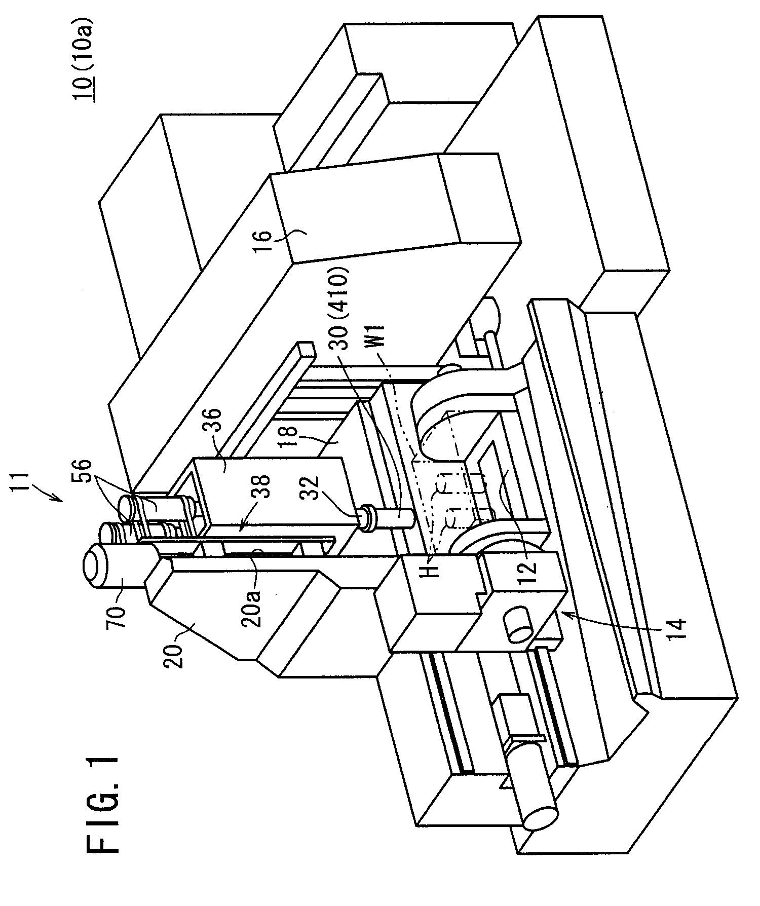
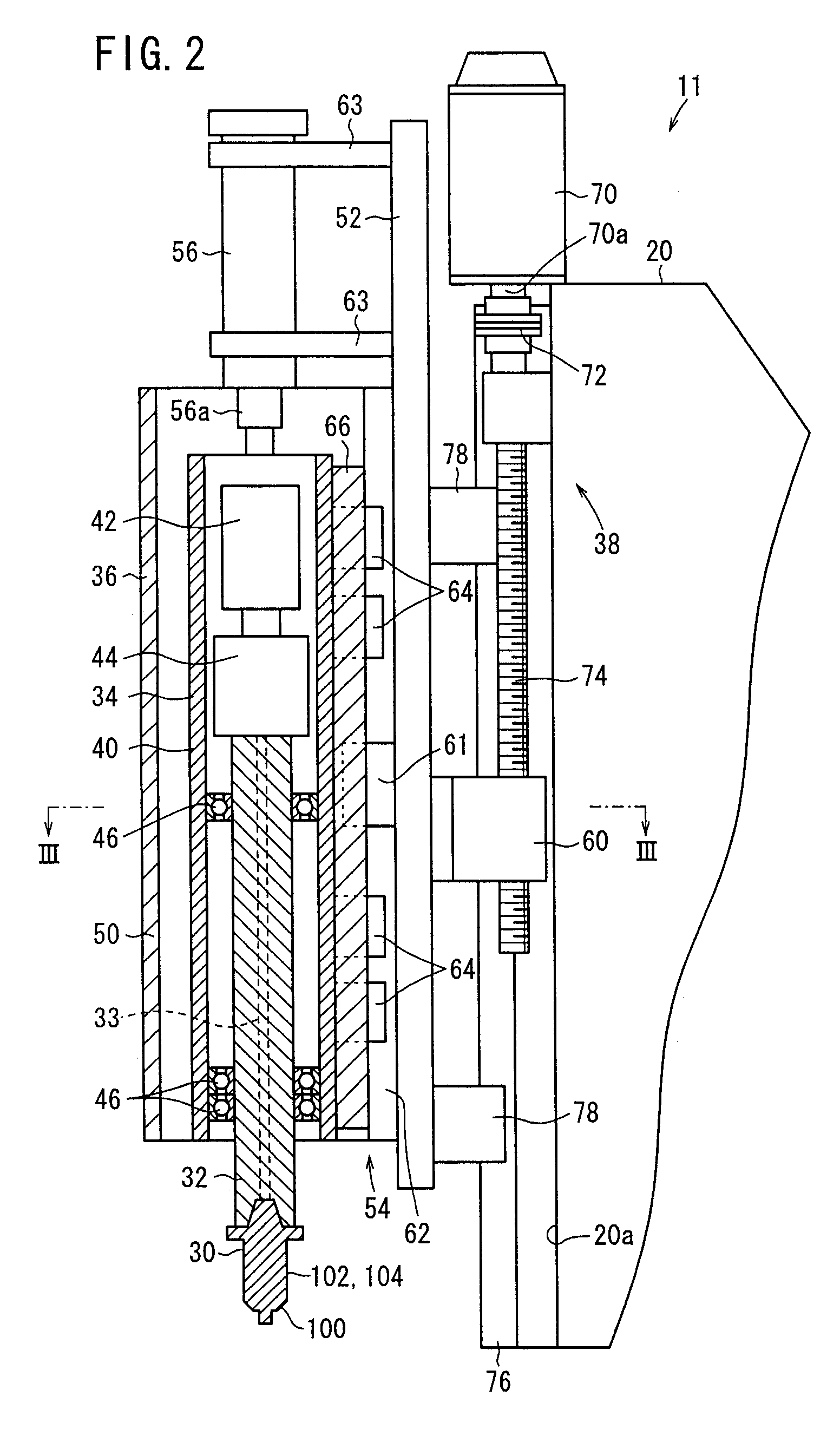
[0089]As shown in FIG. 1, a compound machine tool 10 according to the present invention is disposed in a machining line for machining a cylinder, for example, of an automobile internal combustion engine forming a workpiece W1. The machine tool 10 has a main shaft actuator assembly 11 for actually boring and honing (grinding) the workpiece W1, a workpiece feed mechanism 14 reciprocally movable between a workpiece charger in front of the machine tool and a lower portion of the main shaft actuator assembly 11 for feeding a pallet 12 on which a charged workpiece is placed and fixedly mounted, and a monitoring control console 16 for electrically controlling the main shaft actuator assembly 11 and the workpiece feed mechanism 14. The machine tool 10 is placed as a system in the machining line. The main shaft actuator assembly 11 is mounted on a surface 20a of a column 20 vertically erected on the upper surface of a horizontal base 18 near the workpiece feed mechanism 14, i.e., near the fr...

second embodiment

[0138]A compound machine tool 210 according to the present invention shall now be described below.

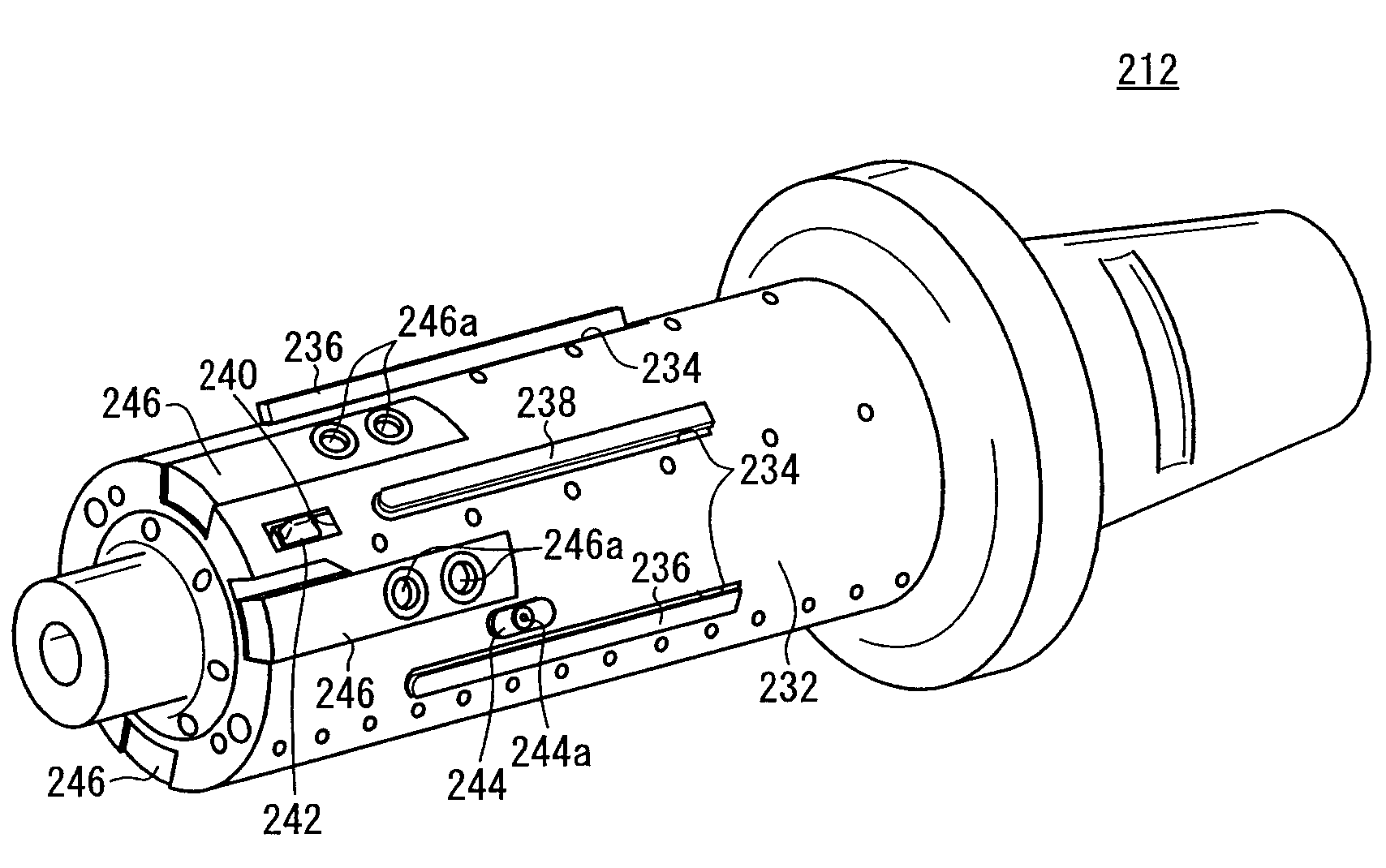
[0139]As shown in FIG. 8, a compound machine tool 210 according to the second embodiment inserts a tool head 212 into a workpiece W2, e.g., a bore in a cylinder block of an automobile engine, and bores and hones the workpiece W2.

[0140]The compound machine tool 210 comprises a tool head (machining head) 212, which is inserted into the workpiece W2, wherein the tool head 212 has a substantially cylindrical shape that can be expanded or contracted in diameter. The compound machine tool 210 further comprises a first gear set 216 and a second gear set 218, a first servomotor 220 and a second servomotor 222 for rotating the first gear set 216 and the second gear set 218, respectively, a main shaft (spindle) 224 to which the tool head 212 is connected, and a moving mechanism (moving means) 226 for axially moving the main shaft 224 back and forth in the directions indicated by the arrow A. The ...

third embodiment

[0205]A tool head (honing tool head or machining head) 410 (see FIG. 23), which can be used on the compound machine tools 10, 210, shall be described below in relation to a machine tool (honing machine tool) 412 that incorporates the tool head 410, according to the present invention.

[0206]As shown in FIG. 23, the machine tool 412 inserts the tool head 410 into a workpiece W3, e.g., a bore in a cylinder block of an automobile engine, and hones an inner circumferential wall surface 414a of the workpiece W3 with the tool head 410.

[0207]The machine tool 412 comprises a tool head 410 that is inserted into the workpiece W3, the tool head 410 being of a substantially cylindrical shape, wherein the tool head 410 can be expanded or contracted in diameter. The machine tool 412 further comprises a first hydraulic cylinder 416 and a second hydraulic cylinder 418 for applying expanding forces to the tool head 410, a control circuit (control means, controller, monitoring control console) 420 for ...


PUM

PropertyMeasurementUnit
rotational poweraaaaaaaaaa
forcesaaaaaaaaaa
diameteraaaaaaaaaa

Abstract

The spindle drive unit of a combined machine tool drives the spindle. The tip end of the spindle is provided with a boring tool and a tool head having a rough grinding stone and a finishing grinding stone. The spindle drive unit has a first support unit and a second support unit capable of receiving the spindle therethrough and supporting it rotatably, a linear motor and a column slide mechanism for moving the first and second support unit in the axis direction of the spindle, and a spindle motor for rotating the spindle.

Description

TECHNICAL FIELD[0001]The present invention relates to a tool head having a grinding tool, a machine tool having a boring tool and a grinding tool, and a method of boring a cylinder block using such a machine tool.BACKGROUND ART[0002]Machining processes for boring cylinder blocks that make up engine components include a boring process (a fine boring process or the like) for forming a bore to a predetermined diameter inside of a cylinder block, and a grinding process (a honing process or the like) for subsequently grinding the bore surface. If the boring and grinding processes can consecutively be performed on a single main shaft of a machine tool, then the cylinder block becomes free of misalignment with the tools, which otherwise would be caused if the cylinder block were moved between different machine tools and chucked again. Therefore, the cylinder block can be machined properly and efficiently. For consecutively performing a boring process and a grinding process, the machine too...

Claims


Application Information

Patent Timeline
Patent Type & Authority Applications(United States)
IPC IPC(8): B23B35/00B23B51/08
CPCB23B41/12B23D77/042B23P23/02B23Q1/4876B24B33/027B24B33/08Y10T29/5176Y10T29/5168Y10T408/36Y10T408/856Y10T408/03Y10T408/375B24B41/04B23B39/00
Inventor SADAOKA, HIDEKIOSHIMA, HIROMINOGAMI, SHINJISUZUKI, MINORUOUCHI, MAKOTOKIKUCHI, MASANORI
Owner HONDA MOTOR CO LTD
Why Eureka
Try Eureka