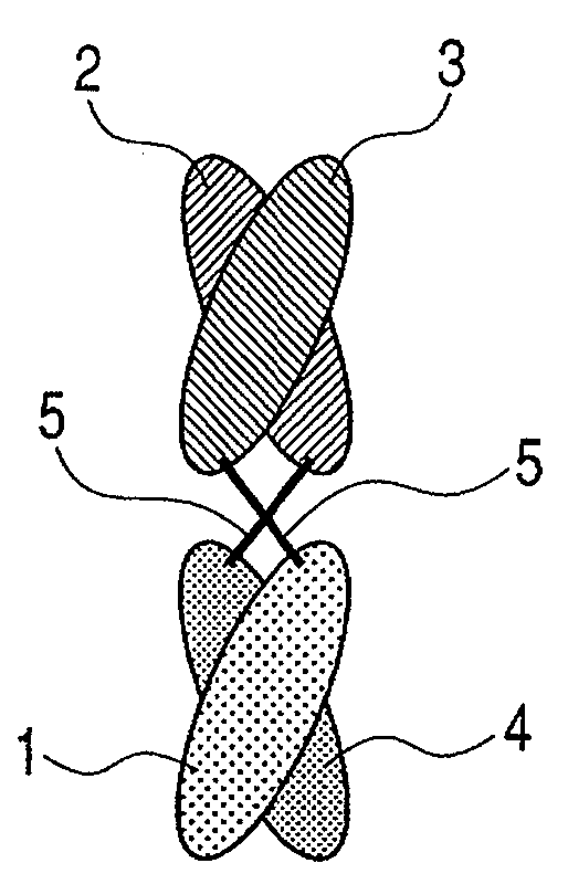
Binding protein molecule
a technology of binding protein and molecule, which is applied in the field of binding protein molecule, can solve the problems of insufficient device technology and limited amount of samples obtained for use achieve the effects of reducing the number of samples used in various detections or searches, and reducing the number of samples used
- Summary
- Abstract
- Description
- Claims
- Application Information
AI Technical Summary
Benefits of technology
Problems solved by technology
Method used
Image
Examples
example 1
Obtainment of PEG- and HEL-Binding Bispecific Antibody Fragments
(1) Preparation of PEG-Binding VH-Coding Nucleic Acid Fragment
[0162]An NcoI restriction site on the 5′-terminal side and an NheI restriction site on 3′-terminal side of the PEG-binding VH (SEQ ID NO: 49 or 50) disclosed in the description of WO 02 / 094853 were located. The PEG-binding VH for introducing vector (hereinafter designated as VH(PEG)) was prepared. Specifically, the overlapping PCR was performed by using following primers and applying a method according to the recommended protocol of the skilled artisan for the commercially available PCR kit to obtain artificial nucleic acids from base pairs of about 350 bp.
PEG-VH F-1(SEQ ID NO: 13)NNNNNCCATGGCAGGTCCAACTGCAGCAGCCCGGTGCTGAGCTTGTGAAGCCTGGGGCCTCAGTGAAGCTGTCCTGCAAGGCTTCTGGPEG-VH F-2(SEQ ID NO: 14)GAAGCAGAGGCCTGGACAAGGCCTTGAGTGGATTGGAAATTCTTATCCTGGTAGTAGTAGTACTAACTACAATGAGAAGTTCAAGAGCPEG-VH F-3(SEQ ID NO: 15)TAGACACATCCTCCAGTACAGCCTACATGCAGCTCAGCAGCCTGACATCTGACGACT...
example 2
Immobilization of Poly(Ethylene Glycol) (PEG) on Gold-Coated Substrate
[0185]Binding ability of the dimeric protein fraction obtained in example 1 on PEG adsorbed on the gold-coated substrate was measured by SPR. BIA core 2000 (BIAcore Inc.) was used as SPR measuring device. Unused SIA-kit Au gold-coated substrate was immersed in ethanol solution of PEG3-OH alkanethiol (Toyobo K. K. SPSPT0011) 10 mg / ml to form monolayer having PEG chain on the surface of gold-coated substrate. After washing the substrate with ethanol solution, the substrate was dried under nitrogen atmosphere. The gold-coated substrate was mounted on the SPR device and the running buffer was injected. After stabilizing SPR signal, 40 μl of 500 nM dimeric protein / PBST solution obtained in example 1 was injected. A curve indicating binding ability to PEG was obtained. Other experimental conditions are shown as follows.
[0186]Temperature: 25° C.
[0187]Flow rate: 1 μl / min.
example 3
Evaluation of HEL-Binding Ability by SPR Measurement
[0188]Subsequent to the sample, which was evaluated the PEG-binding ability by SPR in example 2, 0.5, 1.0 and 2.0 μM HEL / PBST solution was injected consecutively. Binding ability of the dimeric protein fraction, which was bound with the immobilized PEG on the gold-coated substrate, to HEL was measured by SPR. SPR signal intensity shows dependent manner to the HEL concentration. Other experimental conditions are shown as follows.
[0189]Temperature: 25° C.
[0190]Flow rate: 1 μl / min.
PUM
| Property | Measurement | Unit |
|---|---|---|
| Fraction | aaaaa | aaaaa |
| Structure | aaaaa | aaaaa |
| Adsorption entropy | aaaaa | aaaaa |
Abstract
Description
Claims
Application Information
 - R&D
- Intellectual Property
- Life Sciences
- Materials
- Tech Scout
- Unparalleled Data Quality
- Higher Quality Content
- 60% Fewer Hallucinations
Browse by: Latest US Patents, China's latest patents, Technical Efficacy Thesaurus, Application Domain, Technology Topic, Popular Technical Reports.
© 2025 PatSnap. All rights reserved.Legal|Privacy policy|Modern Slavery Act Transparency Statement|Sitemap|About US| Contact US: help@patsnap.com


