Shear stress measurement apparatus

a technology of shear stress and measurement apparatus, which is applied in the direction of mechanical measuring arrangement, force measurement by measuring optical property variation, instruments, etc., can solve the problems of insufficient state of the art to meet all needs, insufficient development of models, and inability to accurately measure wall shear stress

Inactive Publication Date: 2009-05-28
LENTERRA
View PDF10 Cites 27 Cited by
  • Summary
  • Abstract
  • Description
  • Claims
  • Application Information

AI Technical Summary

Problems solved by technology

The accurate measurement of wall shear stress remains a challenge in many industrial applications as well as in scientific research.
Despite the long history of wall shear force measurement attempts using various approaches, the state of the art is still insufficient to meet all needs.
For most applications, these models are not developed sufficiently well and the parameters are not well known.
Laser-based flow velocity methods also require the fluid to be sufficiently transparent for the laser radiation, thus restricting the field of applications of these methods.
This approach, however, does not provide dynamic measurement of the wall shear stress and the spatial resolution can be poor.
Technically, this approach requires covering an extended part of the wall with a film and having optical access to the film that can be difficult to implement in applications other than aerodynamic.
Also, for high levels of shear stress the film may be susceptible to mechanical damage.
These miniature electrical shear stress sensors, while showing satisfactory results in laboratory tests, to date have found limited applications due to following drawbacks:(1) Small dynamic range of shear stress measurement(2) Susceptibility to electromagnetic interference(3) Low sensitivity for piezoresistive MEMS sensors(4) For capacitance-based sensors, it is intrinsically difficult to separate shear stress from pressure (or from the force directed normal to the floating element surface)B.
137-141, 1997).The basic difficulty of this method is the requirement of flow to be transparent for the illuminating laser radiation that should be arranged externally.
The fiber-based Fabry-Perot sensors, however, require a delicate mechanical alignment of the resonator (for example, rotational motion of the floating element may cause significant loss of the resonant signal quality).
Another problem is the need for the Fabry-Perot resonator to be optically clean, a condition that is difficult to sustain in many applications.
The most important drawback of all known direct shear stress measurement methods is the requirement of a sizeable gap between the floating element and the wall, to give room for the floating element to shift under the shear force.
This may cause the inner elements of the sensor to malfunction and may impede the motion of the floating element.
The problem can be solved by inserting a material between the floating element and the wall or by covering the gap from the side of the flow with a flexible material, however, that decreases sensitivity of the sensor and may be unsuitable for chemically active flows.
The efficiency of the coupling will be affected which may lead to the WGM resonance shift caused by a normal force rather than shear force and, thus, to a false reading of the shear stress measurement.

Method used


Image

  • Shear stress measurement apparatus
  • Shear stress measurement apparatus
  • Shear stress measurement apparatus

Examples


second embodiment

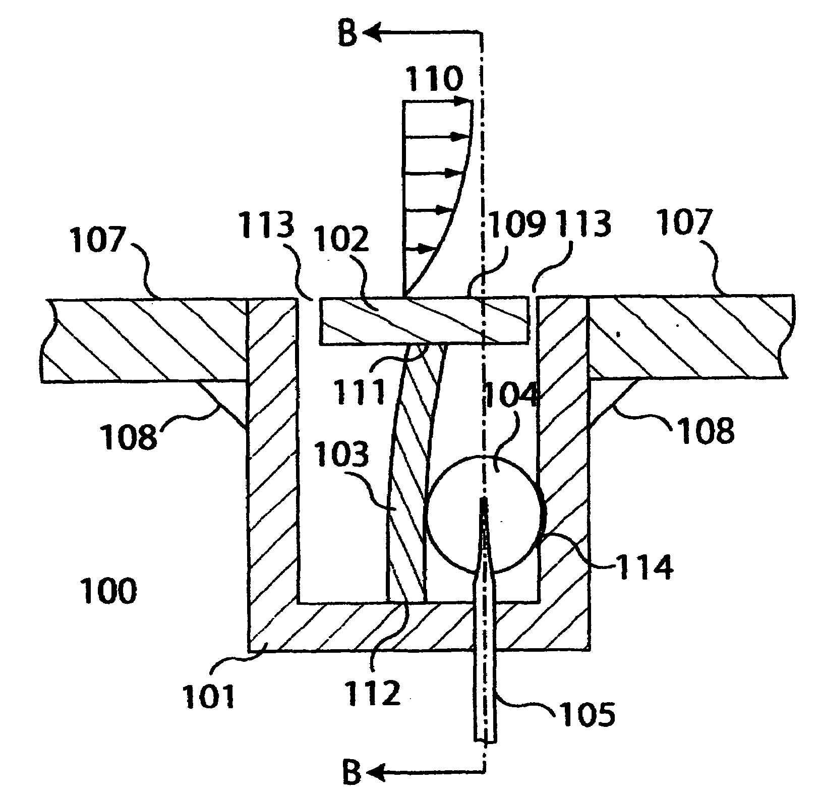
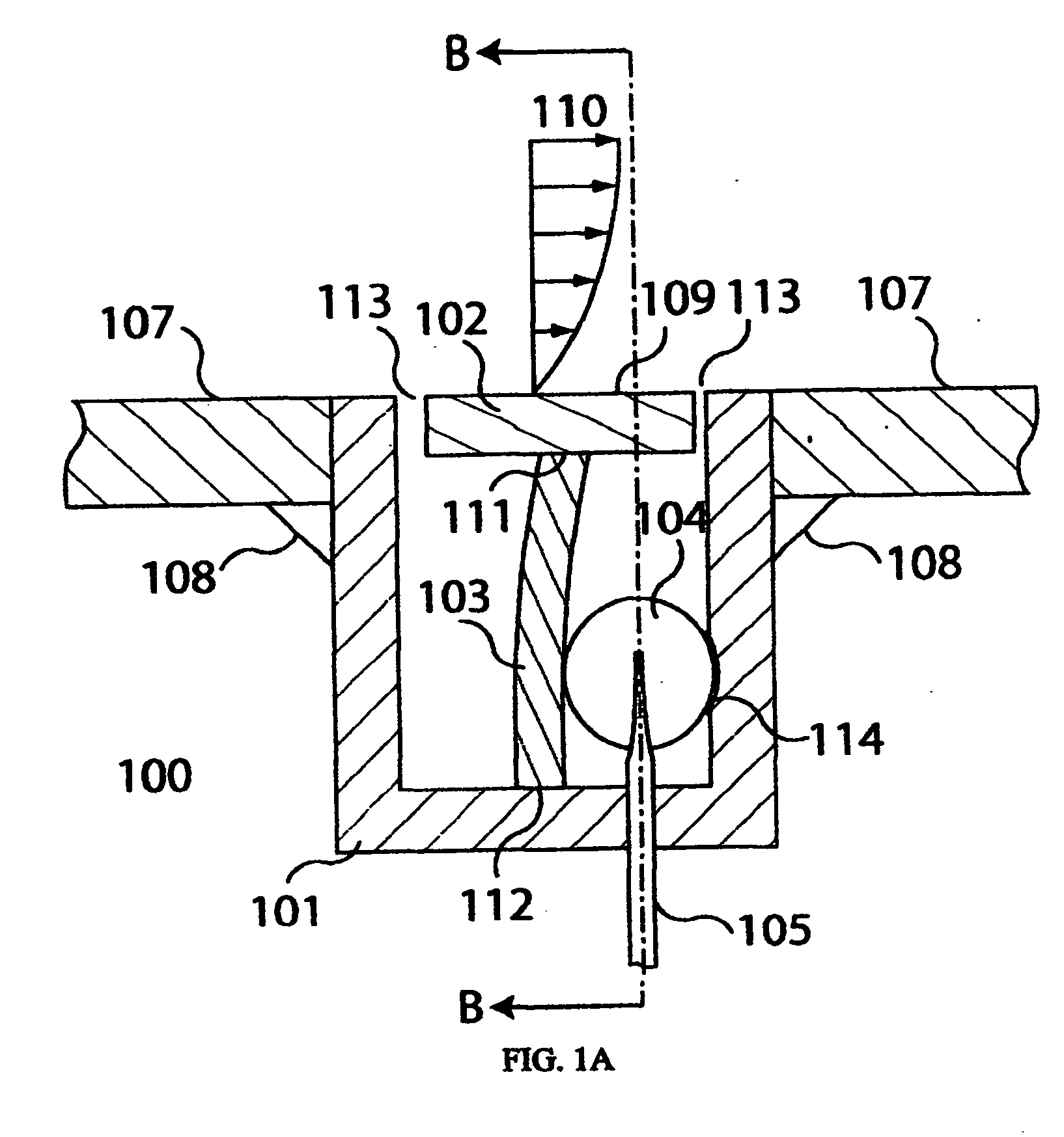
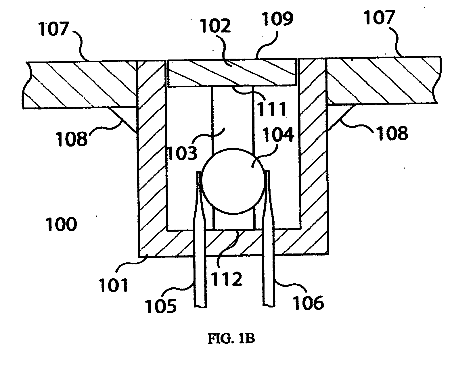
[0049]Micro-resonator 104 may be placed between lever member 103 and the inside wall of base element 101, as shown in FIG. 1A, or between a lever member 201 and a micro-resonator holder member 202, as shown in the FIG. 2, which illustrates shear stress sensor 200 constructed in accordance with the present invention. Components in FIG. 2, corresponding to components in FIGS. 1A and 1B, have been given the same reference numerals used in FIGS. 1A and 1B. Micro-resonator holder member 202 can be formed with an indentation 203 to hold micro-resonator 104 in place and prevent its movement. The position of micro-resonator 104 may be adjusted to initially stress preload (compress) the micro-resonator by means of a preload component, such as a setscrew 204, that moves micro-resonator holder 202 away from or back to the wall of base element 101.

[0050]A third embodiment of a shear stress sensor 300, constructed in accordance with the present invention, is illustrated in FIG. 3, in which compo...

fifth embodiment

[0053]FIG. 5 illustrates a shear stress sensor constructed in accordance with the present invention. The FIG. 5 shear stress sensor is similar to the shear stress sensor of FIGS. 1A and 1B, but adds an environmental sensor 501, for example a thermocouple or a thermistor, that is positioned in proximity to micro-resonator 104 to sense temperature change. Environmental sensor 501 serves in compensating for spectrum shift in the micro-resonator due to the influence of an environmental factor, such as temperature. If the dependence of the spectrum shift versus change in the environmental condition, such as temperature, is known, for example from a theoretical model or from calibration measurements, the measurement results can be adjusted according to the environmental sensor readings.

[0054]A second micro-resonator may serve as a reference for compensating for spectrum shift in micro-resonator 104 due to the influence of an environmental factor. This second micro-resonator would be insta...


PUM

PropertyMeasurementUnit
diameteraaaaaaaaaa
distanceaaaaaaaaaa
sizeaaaaaaaaaa

Abstract

A shear stress sensor for measuring the shear force of a fluid flowing along a wall. A floating member, flush with the wall, senses a shear force of the flowing fluid. The floating member is mounted by support means to a base element that is placed in the wall, so that the floating member is flush with the wall and a shear force, sensed by the floating member, is translated via the support means to a micro-resonator. The force acting on the micro-resonator changes the shape and the refractive index of the micro-resonator, thereby changing the resonant frequency of the micro-resonator and causing a shift in the spectrum of wavelengths of light that is introduced to the micro-resonator. This shift in the spectrum of wavelengths is representative of the shear force of the flowing fluid.

Description

CROSS REFERENCE TO RELATED APPLICATIONS[0001]This application is a non-provisional application based on and claiming the priority of Provisional Application 60 / 990,352 filed Nov. 27, 2007.FIELD OF THE INVENTION[0002]The present invention relates, in general, to measuring wall shear stress (also known as “skin friction”) in fluid flows and, in particular, to apparatus for measuring skin friction by determining the magnitude of a shift in an optical spectrum known as “whispering gallery modes” (WGM).BACKGROUND OF THE INVENTION[0003]The accurate measurement of wall shear stress remains a challenge in many industrial applications as well as in scientific research. Precise knowledge of shear stress can benefit many fields of human activity. For example, it can (a) reduce the cost of manufacturing and increase quality and throughput of certain products in the pharmaceutical, food, paint, and coating industries, and (b) improve the performance of aircraft. The real-time measurement of the ...

Claims


Application Information

Patent Timeline
Patent Type & Authority Applications(United States)
IPC IPC(8): G01L1/24G01N3/24
CPCG01N3/24G01L1/24
Inventor SHEVEREV, VALERY A.STEPANIUK, VADIM
Owner LENTERRA
Why Eureka
Try Eureka