Ac motor and control unit thereof

a technology of ac motor and control unit, applied in the direction of dynamo-electric converter control, magnetic circuit shape/form/construction, electronic commutator, etc., can solve the problems of large outer shape of the motor, unignorable eddy current loss, and large parts removed with portions, so as to reduce size, high performance, and reduce the effect of configuration

Inactive Publication Date: 2009-05-28
DENSO CORP
View PDF14 Cites 52 Cited by
  • Summary
  • Abstract
  • Description
  • Claims
  • Application Information

AI Technical Summary

Benefits of technology

[0025]Combination of the techniques mentioned above may achieve a significantly competitive configuration as a motor with reduced size and high performance or the like. A configuration of a specific combination, for example, may include a stator having loop windings, an axial gap rotor, field windings and diodes of the rotor, and electromagnetic steel plates having insulating films, whose magnetic fluxes can be directed to any directions.
[0026]The excitation currents in the fields can be controlled more effectively by using the configuration in which magnetic poles of the rotor are impa

Problems solved by technology

However, unlike the brushless motor 150 shown in FIGS. 34 to 40, the conventional brushless motor shown in FIGS. 264 and 265 cannot be removed with portions of the winding or cannot have simplified winding for structural reasons.
Thus, a problem arises that the outer shape of the motor tends to become large in order to ensure the space.
However, excessive eddy currents will cause unignorable eddy current loss.
The modifications shown in FIG. 57 enable structuring a motor without using return windings, which has been difficult to achieve with the motor shown in FIG. 29.
As a result, the space factor of the windings in the slots has been reduced to raise a problem of large and long coil ends.
However, behavior of the rotor-side field currents is complicated and is still discussed today in journals of Institute of Electrical Engineers of Japan, for example.
In the motor shown in FIG. 98, the power factor COS(θa) of the stator windings is deteriorated and thus the motor efficiency is deteriorated to problematically increase the size of the motor, and ac

Method used


Image

  • Ac motor and control unit thereof
  • Ac motor and control unit thereof
  • Ac motor and control unit thereof

Examples


Embodiment Construction

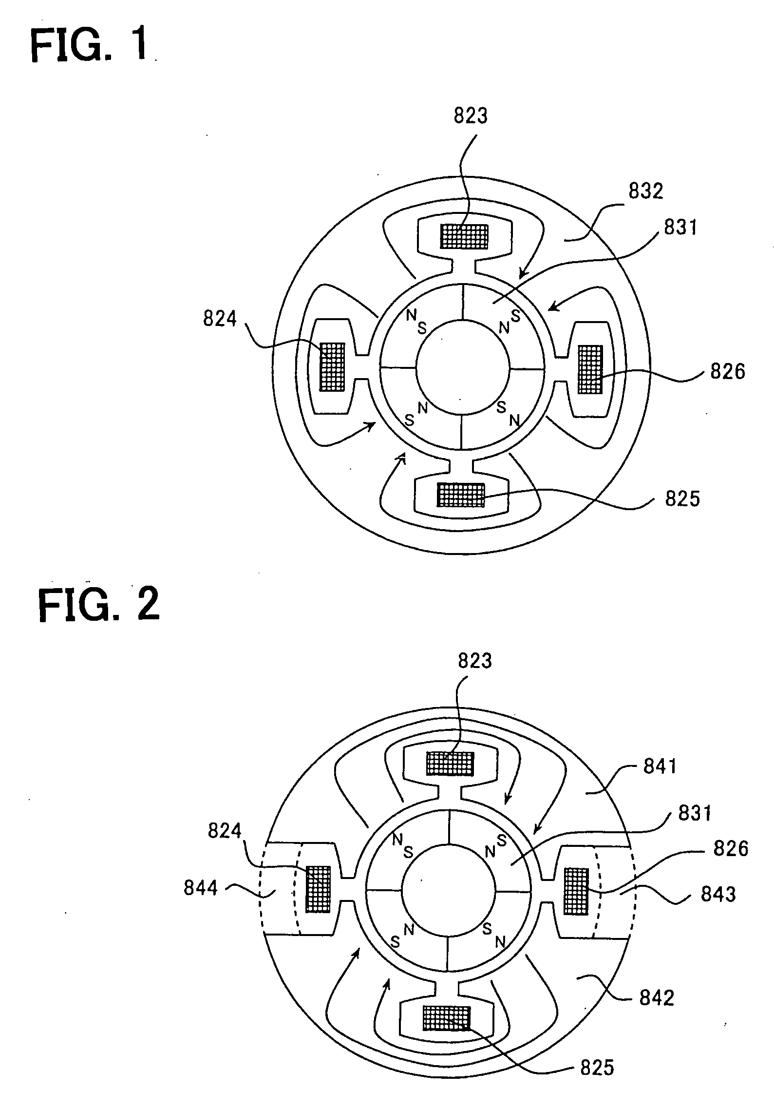
[0133]With reference to the drawings, hereinafter will be described, in detail, motors according to various embodiments to which the present invention is applied.

[0134]FIG. 1 shows a single-phase four-pole AC motor. Indicated by numeral 831 are permanent magnets for a rotor, by 832 is a stator core made of soft magnetic material, and by 823, 824, 825 and 826 are single-phase windings. Some methods may be provided in giving turns of the windings. One example is to give turns of the windings 823 and 824 to obtain single-phase windings, and to give turns of the windings 825 and 826 to obtain single-phase windings. In this case, the maximum amount of magnetic fluxes interlinking with the winding 823 shown in FIG. 1 corresponds to ½ of magnetic fluxes of one magnetic pole of the permanent magnet 831.

[0135]FIG. 2 shows a motor of FIG. 1 but with portions 843 and 844 shown by broken lines being cut and removed. In this case, the maximum amount of magnetic fluxes interlinking with the windi...


PUM


Abstract

The motor, which is an incorporated N-phased motor, comprises a rotor having four or more poles with N-poles and S-poles being alternately arranged in the circumferential direction, a stator having a stator core in which magnetic circuits are magnetically separated within an electrical angle of 360°, and an (N−1) number (N is a positive integer) of windings. The motor is configured so that currents of the windings can effectively work on the magnetic circuits.

Description

TECHNICAL FIELD OF THE INVENTION[0001]The present invention relates to a motor which is loaded, for example, on an automobile or a truck.TECHNICAL BACKGROUND[0002]Brushless motors have been known, in which coils of individual phases are concentrically wound about the stator poles (see, for example, Patent Document 1). FIG. 95 is a schematic vertical cross section illustrating such a conventional brushless motor. FIG. 97 is a cross section taking along a line AA-AA of FIG. 95.[0003]These figures show a four-pole six-slot type brushless motor having a stator with a so-called concentrated winding structure, in which coils of individual phases are concentrically wound about the stator poles. FIG. 96 is a circumferential development of one cycle of the stator, which indicates an arrangement relationship of windings U, V and W or the like. The horizontal axis indicates electrical angle, with one cycle being 720°. Permanent magnets of N- and S-poles are alternately arranged in the circumfe...

Claims


Application Information

Patent Timeline
IPC IPC(8): H02K19/10H02P6/14H02K1/12H02K1/14H02K3/04H02P21/00H02P21/13H02P27/04
CPCB60L7/00B60L2210/20H02K1/141H02K1/145H02K1/148Y02T10/725H02K21/145H02K21/16H02K2201/12Y02T10/641H02K19/103Y02T10/64Y02T10/72H02K19/12
Inventor NASHIKI, MASAYUKI
Owner DENSO CORP
Why Eureka
Try Eureka