Organic Electroluminescent Element, Production Method of the Same, Display Device, and Lighting Device

Active Publication Date: 2009-05-28
MERCK PATENT GMBH
View PDF2 Cites 8 Cited by
  • Summary
  • Abstract
  • Description
  • Claims
  • Application Information

AI Technical Summary

Benefits of technology

[0018]The present invention enables to provide an organic EL element exhibiting high light emission luminance, a production method

Problems solved by technology

However, since vapor deposition is carried out under high vacuum of at most 10−4 Pa, operation becomes complex, resulting in an increase in cost, whereby preference is not always realized in terms of production.
Specifically, for lighting applications, it is essential to form an organic EL element of a large area, whereby vapor deposition becomes a difficult production process.
Further, in regard to a phosphorescent dopant which is employed in phosphorescence emitting organic EL elements, it is difficult to introduce, to an organic EL element, a plurality of uniform dopants of a large area via vapor deposition.
Consequently, in terms of cost and technology, such process is currently considered to be very difficult.
Further, since a thin film is produced employing a previously

Method used


Image

  • Organic Electroluminescent Element, Production Method of the Same, Display Device, and Lighting Device
  • Organic Electroluminescent Element, Production Method of the Same, Display Device, and Lighting Device
  • Organic Electroluminescent Element, Production Method of the Same, Display Device, and Lighting Device

Examples


examples

Preparation of Organic EL Element 1

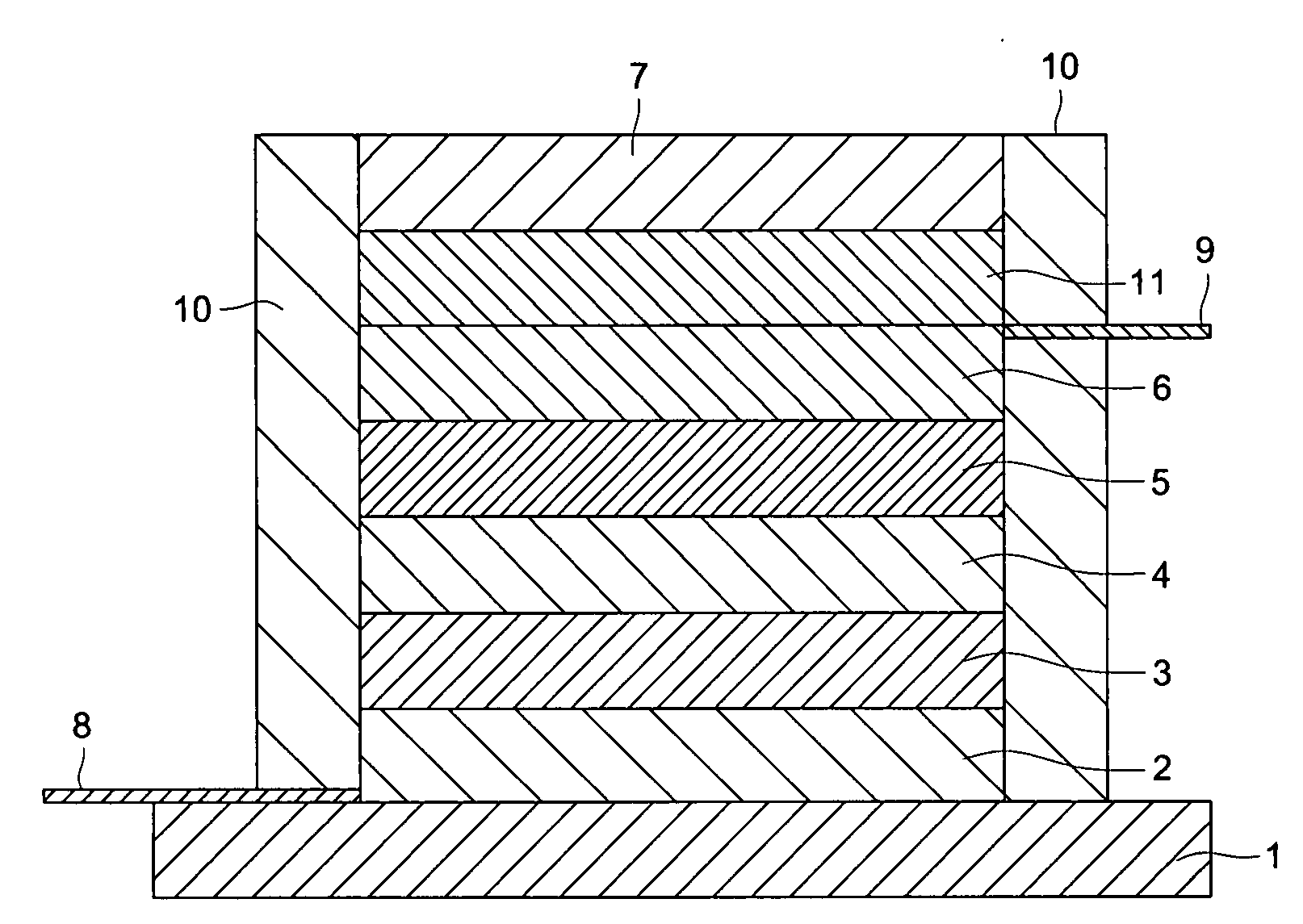
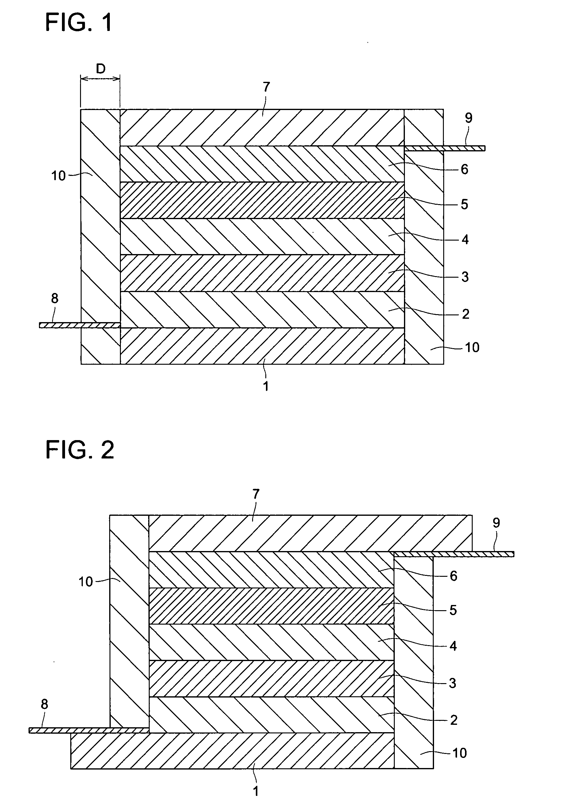
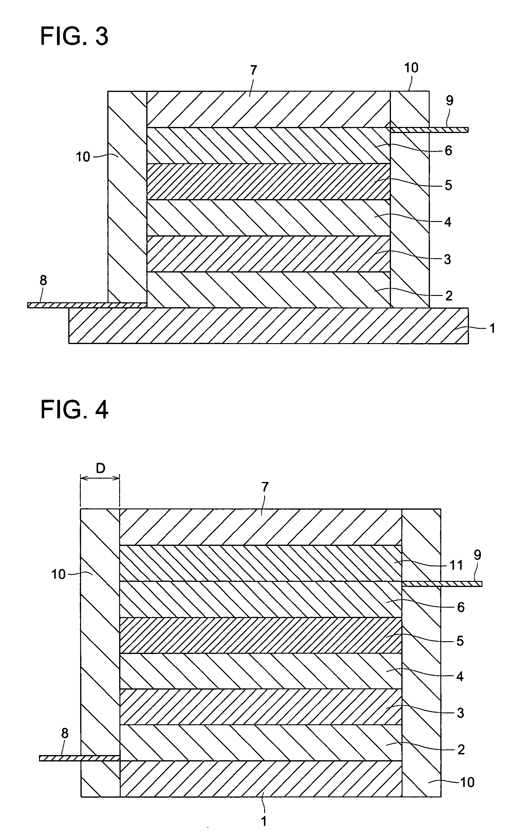
[0286]Full-color Organic EL Element 1 composed of a cathode substrate / cathode / electron transporting layer / light emitting layer / positive hole transporting layer / anode / anode substrate was prepared as described below.

(A) Preparation of Cathode Laminated Body 1 (Anode Substrate / Anode / Electron Transporting Layer)

[0287]Both sides of a sheet of Al foil (at a thickness of 30 μm) was laminated with a 50 μm thick polyimide sheet (UPILEX 50S, produced by Ube Industries, Ltd.), and the resulting foil was cut to 35 mm×40 mm, whereby a cathode substrate was prepared.

[0288]The above cathode substrate was placed in a cleaning vessel. After cleaning it via i-propyl alcohol (IPA), it was subjected to oxygen plasma treatment. Subsequently, a mask (a mask arranged with stripes of a line width of 300 μm and an interval of 30 μm, as shown in FIG. 12) was arranged, and Al was vapor-deposited at a reduced pressure of about 0.1 mPa, whereby a stripe-structured cathode of a...

example 2

[0304]As described below, full-color Organic EL Element 2 was prepared, which was composed of a cathode substrate / cathode / electron transporting layer / light emitting layer / positive hole transporting layer / anode / anode substrate.

(A) Preparation of Cathode Laminated Body 2 (Cathode Substrate / Cathode / Electron Transporting Layer)

[0305]Both sides of an Al foil (at a thickness of 30 μm) was laminated with a 50 μm thick polyimide sheet (UPILEX 50S, produced by Ube Industries, Ltd.), and the resulting foil was cut to 35 mm×40 mm, whereby a cathode substrate was prepared.

[0306]The above cathode substrate was placed in a cleaning vessel. After cleaning it via i-propyl alcohol (IPA), an oxygen plasma treatment was applied. Subsequently, a mask (a mask arranged with stripes of a line width of 300 μm and an interval of 30 μm, shown in FIG. 12) for deposition, which was subjected to patterning, was arranged, and Al was vapor-deposited at a reduced pressure of about 0.1 mPa, whereby a stripe-structu...

example 3

Preparation of Organic EL Element 3

[0323]As described below, full-color Organic EL Element 3 was prepared, which was composed of a cathode substrate / cathode / electron transporting layer / light emitting layer / positive hole transporting layer / anode / anode substrate.

(A) Preparation of Cathode Laminated Body 3 (Cathode Substrate / Cathode / Electron Transporting Layer)

[0324]Both sides of an Al foil (at a thickness of 30 μm) was laminated with a 50 μm thick polyimide sheet (UPILEX 50S, produced by Ube Industries, Ltd.), and the resulting foil was cut to 35 mm×40 mm, whereby a cathode substrate was prepared.

[0325]The above cathode substrate was placed in a cleaning vessel. After cleaning it with i-propyl alcohol (IPA), an oxygen plasma treatment was applied. Subsequently, a mask (a mask arranged with stripes of a line width of 300 μm and an interval of 30 μm, shown in FIG. 12) for deposition, which was subjected to patterning, was arranged, and Al was vapor-deposited at a reduced pressure of abo...


PUM

PropertyMeasurementUnit
Percent by massaaaaaaaaaa
Temperatureaaaaaaaaaa
Thicknessaaaaaaaaaa

Abstract

An organic electroluminescent element comprising a laminated body incorporating an anode substrate, an anode, at least one non-light emitting organic layer A exhibiting positive hole transportability, at least one light emitting organic layer B, at least one non-light emitting organic layer C exhibiting electron transportability, a cathode, and a cathode substrate in the sequence set forth, wherein at least 80% by weight of the organic layer A and the organic layer C in the laminated body is formed via a wet process, and the laminated body is made with an adhesion process between the organic layer A and the organic layer B, or between the organic layer B and the organic layer C.

Description

TECHNICAL FIELD[0001]The present invention relates to an organic electroluminescent element, a production method of the same, a display device, and a lighting device, and in more detail, to an organic electroluminescent element exhibiting high efficiency at low cost, a production method of the same, a display device, and a lighting device.BACKGROUND[0002]In recent years, the use of organic electroluminescent (EL) elements has been investigated in display devices such as a flat display and light sources in electrophotographic copiers and printers.[0003]The above organic EL elements are electric current driving type light emitting elements in which a very thin film of fluorescent organic compounds is sandwiched between an anode and a cathode, and light is emitted due to flow of the electric current. Generally, organic materials are insulators, but it is possible to inject an electric current when the thickness of the organic layer is markedly decreased, whereby it is possible to drive...

Claims


Application Information

Patent Timeline
IPC IPC(8): H01J1/62H01L21/02
CPCH01L27/3211H01L51/0003H01L51/0013H01L51/56H01L51/0085H01L51/5237H01L51/0042H10K59/35H10K71/12H10K71/18H10K85/146H10K85/342H10K50/8426H10K50/846H10K71/00
Inventor NISHIZEKI, MASATOSUZURI, TOSHIYUKI
Owner MERCK PATENT GMBH
Why Eureka
Try Eureka