Optical Cavity for Gas Sensor

a gas sensor and optical cavity technology, applied in the field of optical cavity for an infrared (ndir) gas sensor, can solve the problems of reducing the competitiveness of a product, increasing the volume of gas sensor and related manufacturing cost, and large deviation in the performance of each product, so as to reduce trial and error and cost, and easy to analyze

Active Publication Date: 2009-05-28
ELT
View PDF1 Cites 8 Cited by
  • Summary
  • Abstract
  • Description
  • Claims
  • Application Information

AI Technical Summary

Benefits of technology

[0014]Other object of the present invention is to effectively design the optical cavity that is an essential component of an NDIR gas sensor to have an extended optical path to get an increase in the measurement precision and accuracy, and to have a substantially increased ventilating opening size to facilitate the in and out of the target gas through the optical cavity thereby decreasing the response time required for measuring the gas concentration one time.
[0016]Another object of the present invention is to provide an optical cavity having a ventilating opening of a great size for facilitating the thermal radiation through the ventilating opening to prevent the measurement error due to the temperature rise within the optical cavity.
[0017]Another object of the present invention is to provide an optical cavity that is capable of facilitating the gas inflow and outflow and preventing the temperature rise within the optical cavity due to unnecessary optical paths having many light reflections that are not detected by the light detector by inducing the radiated light to be reflected at a predetermined section on the plane mirror and employing the ventilating opening in other section of the plane mirror without the light reflection.
[0019]Another object of the present invention is to provide an optical cavity that enables the cavity designers to design the cavity with a simple geometric figure than can be easily analyzed and to easily change the optical path by changing a minimum number of cavity design factors thereby reducing the trial and error and cost for designing the optical cavity.
[0020]Another object of the present invention is to provide an optical cavity of which the optical path can be easily adjusted by controlling the ratio of focal distances of two quadratic parabolic mirrors and that is easy to be designed based on the applied gas type.
[0021]Another object of the present invention is to provide an optical cavity that is capable of conversance the radiated light having an expanded light beam size from its original state by reflecting the light to pass through a predetermined focus.

Problems solved by technology

However, simply increasing the optical cavity to get extended optical path may reduce the competitiveness of a product by causing an increase in the volume of the gas sensor and related manufacturing cost.
However, in the optical simulation, too many factors may affect the performance of the optical cavity and the accumulation of a number of small error factors occurring in the designing and manufacturing process of an optical cavity may result in a great deal of deviation in the performance of each product as well as a lot of time and cost consumption for the recovery of errors.
Further, in designing an optical cavity using the optical simulation technique, one has to redesign the optical cavity by trial and error process in order to increase or decrease the length of the optical path with a given sized optical cavity and may obtain an impractical optical cavity that cannot be applied to a given gas sensor circuit.
Under this situation, however, the space for gas ventilating opening shall be relatively reduced to cause the response time (i.e. time period required for one time measurement) to be excessively extended.
That is, it might take several minutes to measure the gas concentration one time and thus the conventional gas cavity with a small space for gas ventilating opening could not be used in a sensing environment requiring a rapid measuring speed (or a short response time).
For example, when a light beam having energy of 100 is radiated from the light source a greater energy of more than 100 can be formed due to the temperature rise in the optical cavity, which results in the measurement error.
However, efficient gas measurement may not be possible due to the small intensity of radiation at the light detector with a pulse type light beam of a small pulse width.
In contrast, the use of a pulse type light beam of a large pulse width may affect the temperature rise inside the optical cavity and thus cause to incur the measurement error of the gas sensor.
Still further, since the characteristic of optical cavity including the length of optical path may be affected by various factors it is not easy to modify the design variables by repeated experiment after designing an optical cavity or to predict the characteristic change of the optical cavity and reflect the change onto the cavity design.
Since the light beam radiated from the light source has a predetermined beam width or beam size it is not possible to make all the radiated light to have an ideal optical path passing through a light focus.
Therefore, it is very hard to design an optical cavity in consideration of the various optical paths that arise inside the optical cavity.

Method used


Image

  • Optical Cavity for Gas Sensor
  • Optical Cavity for Gas Sensor
  • Optical Cavity for Gas Sensor

Examples


Embodiment Construction

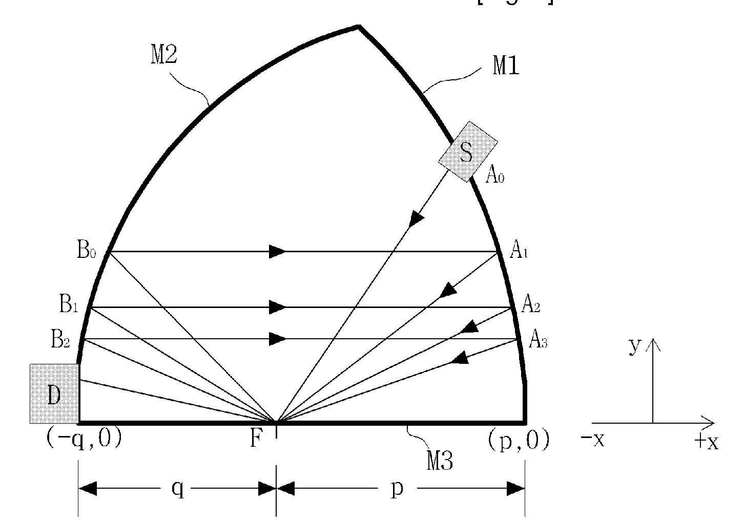
[0032]For the aforesaid object, the optical cavity according to one aspect of the present invention comprises two oppositely arranged parabolic mirrors having common focus located on the common optical axis of the parabolic mirrors; and a plane mirror arranged along the optical axis between the vertexes of each of the parabolic mirrors.

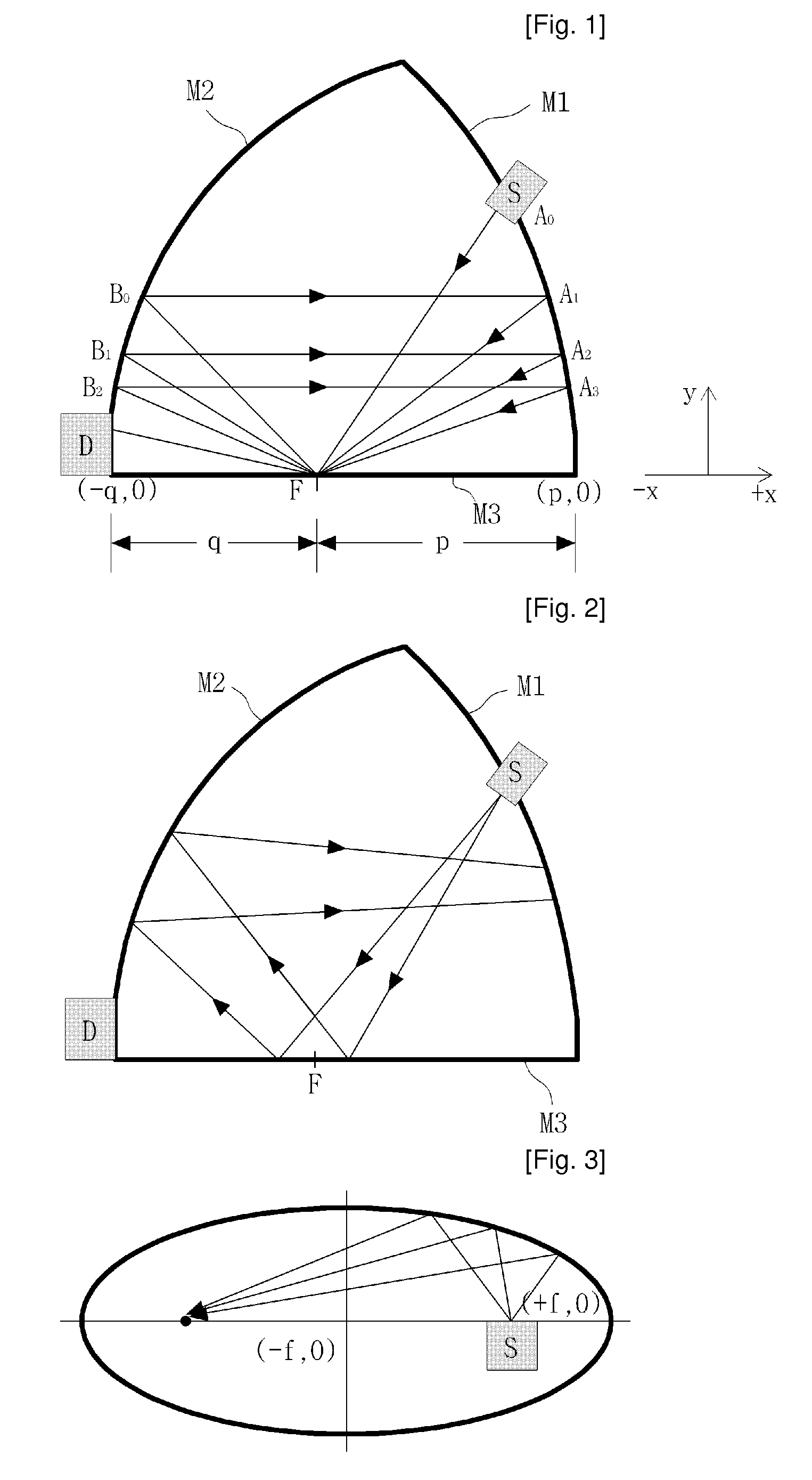
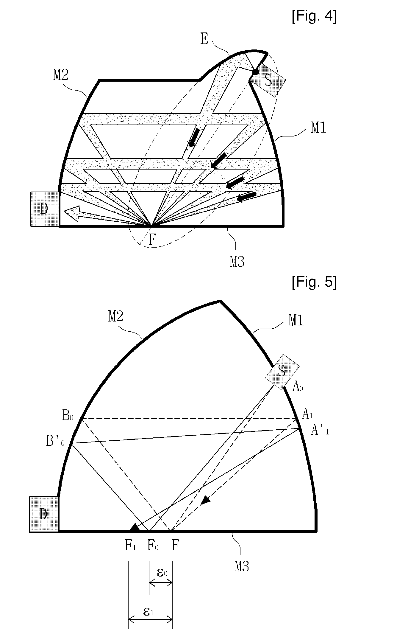
[0033]In the above-mentioned optical cavity, the light radiated from an arbitrary point on the parabolic mirror having longer focal distance circulates the inside of the optical cavity, goes along the optical axis to the positive and negative directions, and finally converges into the optical axis. Therefore, a light detector located in parallel to the optical axis can detect all the lights radiated from the light source.

[0034]In the above-mentioned optical cavity, light reflection occurs only at the focal point of the parabolic mirrors on the plane mirror. Since light reflection occurs only at the focal point located on the plane mirror the light doe...


PUM

PropertyMeasurementUnit
focal distanceaaaaaaaaaa
angle of radiationaaaaaaaaaa
lengthaaaaaaaaaa

Abstract

An optical cavity for a Non-Dispersive Infrared gas sensor has invented comprising two oppositely arranged parabolic mirrors having common focus located on the common optical axis of the parabolic mirrors, and a plane mirror arranged along the optical axis between the vertex of each of the parabolic mirrors. The NDIR gas sensor has an extended optical path to increase precision and accuracy in the measurement, and substantially increased ventilation opening size to facilitate in and out of the target gas through the optical cavity thereby decreasing the response time required for measuring the gas concentration. The sensors based on the principal of Non-Dispersive Infrared Detection is used the light-absorbing characteristic of gases to measure the amount of light absorption that occur at the specific wavelength absorbed by a target gas and calculate the target gas concentration.

Description

BACKGROUND OF THE INVENTION[0001]1. Field of the Invention[0002]The present invention relates to an optical cavity for an Non-Dispersive Infrared (NDIR) gas sensor. More specifically, the sensors based on the principal of Non-Dispersive Infrared Detection uses the light-absorbing characteristic of gases to measure the amount of light absorption that occur at the specific wavelength that is absorbed by a target gas and calculate the target gas concentration.[0003]2. Related Prior Art[0004]An NDIR gas sensor normally comprises a gas chamber consisting of optical cavity, light source and light detector, and electronic circuits that analyze the electric signal from the light detector to get gas concentration.[0005]In general, in order to obtain an NDIR gas sensor of superior quality with higher precision and accuracy, it is important to extend the length of the optical path within a given optical cavity so that the amount of absorbed light during the propagation of the light within the ...

Claims


Application Information

Patent Timeline
Patent Type & Authority Applications(United States)
IPC IPC(8): G01N1/10
CPCG01N21/031G01N21/61G01N21/3504G01N21/4738G01N21/5911G01N21/783
Inventor PARK, JEONG-IK
Owner ELT
Why Eureka
Try Eureka