Power line temperature and sag monitor system

Active Publication Date: 2009-05-28
ATECNUM CORP
View PDF9 Cites 24 Cited by
  • Summary
  • Abstract
  • Description
  • Claims
  • Application Information

AI Technical Summary

Benefits of technology

[0018]The present invention provides a simplified, accurate and easy to use, time sensitive system of monitoring sag in power transmission lines.

Problems solved by technology

One hurdle to increased power transmission is clearance between the power line and the ground or structure.
Thus, clearance can be is one of the considerations to electrical utilities because power lines sag under increasing power loads and as a result limitations are placed on the ampacity or maximum load a line is allowed to carry.
As load increases more heat is generated resulting in ever increasing 
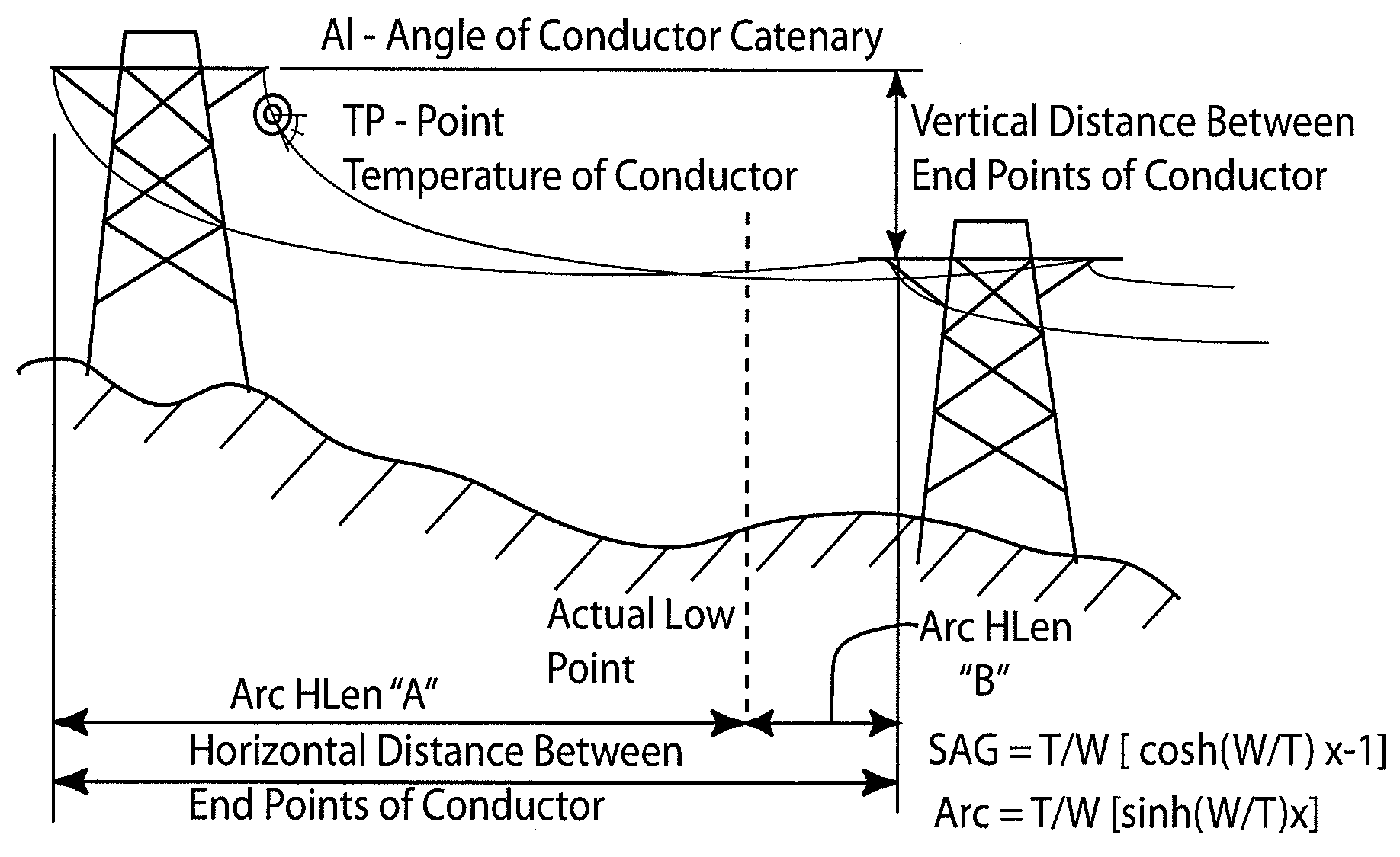
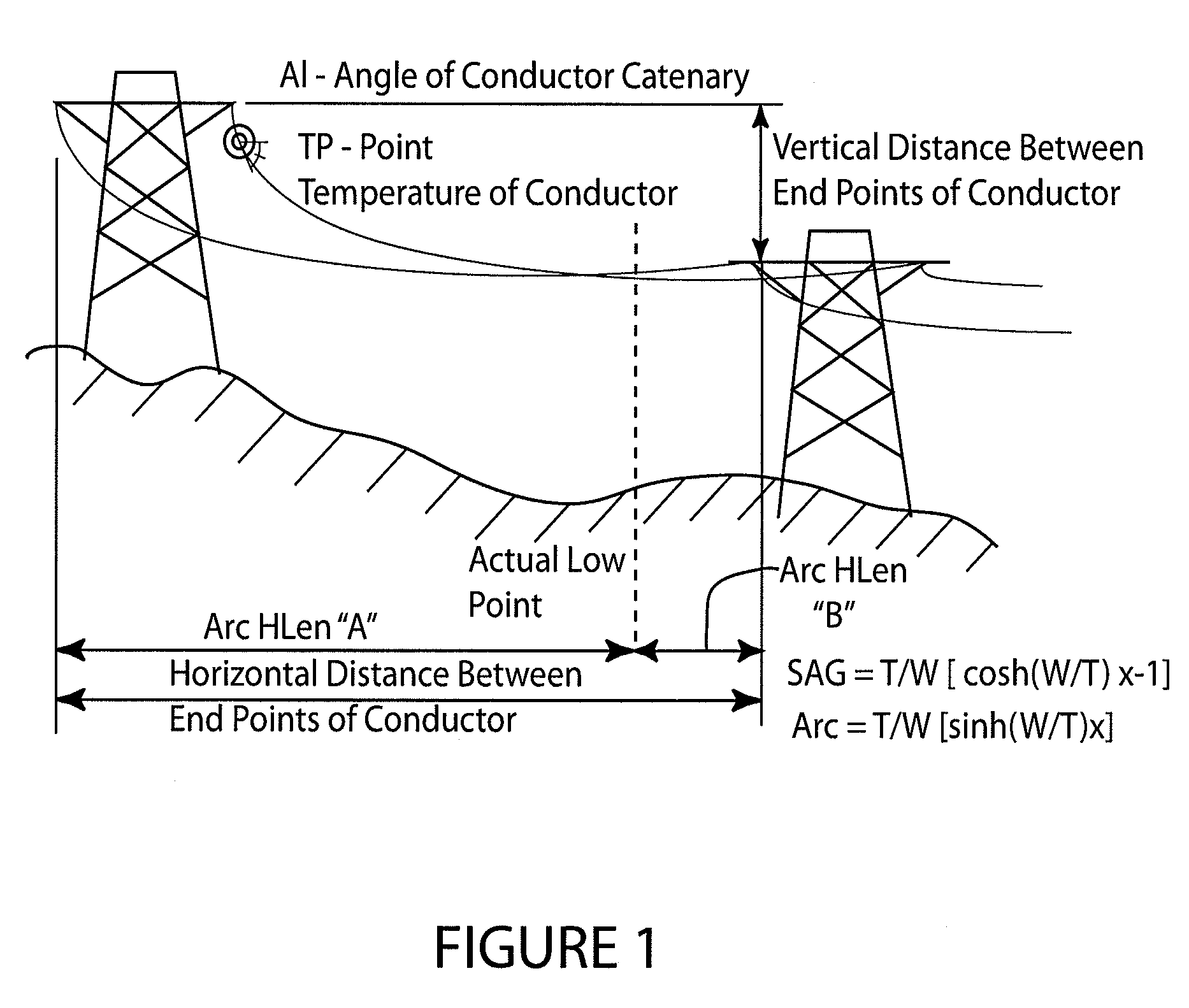
thermal expansion of the power line causing the power line to sag closer to the ground.
It is often typical that safety is a significant factor and thus maximum load is significantly affected.
Adequate clearance regulations are necessary because power lines, after being installed in relation to the ground or structures, may later sag so as to become too close to the ground or structures resulting in significant safety concerns.
One such concern is that when power lines sag too close to the ground, electrical shock or contact with the lines becomes more feasible and thus safety is at issue.
Another such concern is that electric flashover scenarios are possible as lines become too close to electrically grounding objects such as the ground or structures, and such electric flashover can result in extensive damage.
It is noteworthy though that such conservative assumptions result in significantly less than maximum line loading.
However, once an electrical load is placed on the power lines, various load factors cause the power lines to sag.
Some of the problems of this method are due to its approximating qualities rather than accurate calculations.
Other disadvantages and / or problems result from the inability to measure the temperature at all points, instead of sample points.
As a result of these and other disadvantages and problems, additional safety factors may need to be added to assure minimum clearances, but as a result optimization suffers.
This approach is time consuming, labor intensive, indirect and often subject to large errors.
These disadvantages may include conservative current ratings resulting from an assumed combination of worst case cooling conditions.
These measurements may be done with actual measuring, using acoustics, microwaves, and laser beams, although none of these methods may be practical.
The equipment can be bulky, heavy and expensive.
The equipment is typically installed on the ground under the conductor and thus must be left unattended where it is subject to vandalism, and it reduces the clearance at the center portion of the line where it is installed.
There are limitations and / or disadvantages associated with this tension measuring method.
Second, often load cells must be installed in-line which requires de-energizing and cutting of the line; and as a result, significant labor expense and line downtime is incurred.
Finally, many of the current tension reading load cells must be installed on the grounded end of insulators holding the line at dead-end structures; and as a result, calculations cannot be performed on all spans.

Method used


Image

  • Power line temperature and sag monitor system
  • Power line temperature and sag monitor system
  • Power line temperature and sag monitor system

Examples


Embodiment Construction

[0036]A new process for determining the average temperature and sag of a high voltage overhead electrical conductor is described herein. The technique uses conductor temperature measurements and either the angle of inclination or tension measurements from overhead line conductors, and incorporates that data into a digital, statistical estimator to derive the average conductor temperature and sag for the entire overhead span. The resultant temperature may be further used as in input to a dynamic rating algorithm.

[0037]The catenary equation describes the shape of an overhead electrical wire conductor suspended between two towers and the catenary equation can be used to compute the sag of the conductor relative to the end attachment points and the horizontal component of the tension in the conductor anywhere on the span.

[0038]The catenary equation is provided as Equation 1. A catenary is defined as the curve assumed by a hanging flexible wire conductor or chain when supported at its en...


PUM


Abstract

The combination of a temperature sensor and an inclination sensor or the combination of a temperature sensor and a tension monitor properly positioned in conjunction with an energized electrical conductor produces outputs that are dependent on the conductor's average temperature in real time. A transmitter is used to communicate this information in real time to a central location such that up to optimal or maximum power transmission is feasible through the conductor while maintaining a safe clearance to the ground. This allows for close monitoring of thermal expansion resulting from increased load as well as varying environmental conditions.

Description

[0001]This is a continuation of International Application PCT / US2007 / 068429, filed May 8, 2007.BACKGROUND OF THE INVENTION[0002]1. Technical Field[0003]The invention relates to an apparatus and method of monitoring the average temperature in energized electrical conductors such as power lines so as to assure safe clearance from the ground. More particularly, the invention relates to an apparatus and method for measuring the temperature and sag of energized electrical conductors such as power lines in real time as they change with varying electrical load on the line as well as varying environmental conditions causing thermal expansion where the temperature monitor assists in the determination of the maximum power transmission feasible through such conductor while maintaining safe clearance from the ground.[0004]2. Background Information[0005]With deregulation of utilities including electrical utilities, it is now more important than ever that utilities be efficient in the delivery of...

Claims


Application Information

Patent Timeline
IPC IPC(8): G01K13/00G06F17/15G06F17/18
CPCG01C9/00G01K13/00G01K7/42G01K3/06
Inventor ENGELHARDT, JOHNFISH, LARRY
Owner ATECNUM CORP
Why Eureka
Try Eureka