Sputtering apparatus and sputtering method

a sputtering apparatus and sputtering technology, applied in the direction of vacuum evaporation coating, electrolysis components, coatings, etc., can solve the problems of difficult to arrange the magnetic lobe, difficult to achieve the arrangement of the magnetic lobe, and poor quality of products, so as to increase the use efficiency of the target material and reduce the effect of dus

Active Publication Date: 2009-06-04
PANASONIC CORP
View PDF4 Cites 14 Cited by
  • Summary
  • Abstract
  • Description
  • Claims
  • Application Information

AI Technical Summary

Benefits of technology

[0031]According to the sputtering apparatus and the sputtering method of the present invention, a line of magnetic force may be generated nearly in parallel to a target surface in a wide region near the surface of the target, and thus electrons may be trapped in a wide region. Therefore, plasma may be generated in a wide region near the surface of the target, and the use efficiency of the target material can be increased. For example, according to the present invention, the use efficiency of the target material, which has been approximately 10 to 20% conventionally, may be improved up to approximately 40%.
[0032]Further, since sputtering may be carried out in a wide region near the target, film may be prevented from re-adhesion, and abnormal electric discharges may be controlled, and as a result, dusts may be reduced.

Problems solved by technology

Since this change affects the film-forming rate, in-plane homogeneity of the film thickness, and the like, it causes the quality deterioration of products, and yield degradation.
On the other hand, when the magnetic circuit is installed in the outside of the cooling channel, since the interval from the magnetic circuit to the target surface becomes long, it is difficult to arrange the magnetic lobe in the sputtering region, and the shape of the line of magnetic force in the vicinity of the target surface becomes a limited shape close to a magnetic loop by a simple double ring magnet, and there is a tendency that it is difficult to form a line of magnetic force in parallel to the target surface.
H11-500490, and The U.S. Pat. No. 4,964,968, it is difficult to generate plasma in a wide region near the surface of the target, and the material use efficiency is not improved sufficiently.
As a result, dusts or abnormal electric discharges are caused, and the quality of the sputter film to be manufactured may be deteriorated.

Method used


Image

  • Sputtering apparatus and sputtering method
  • Sputtering apparatus and sputtering method
  • Sputtering apparatus and sputtering method

Examples


embodiment 1

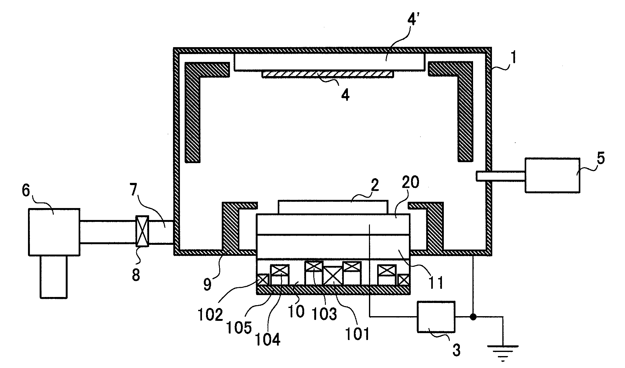
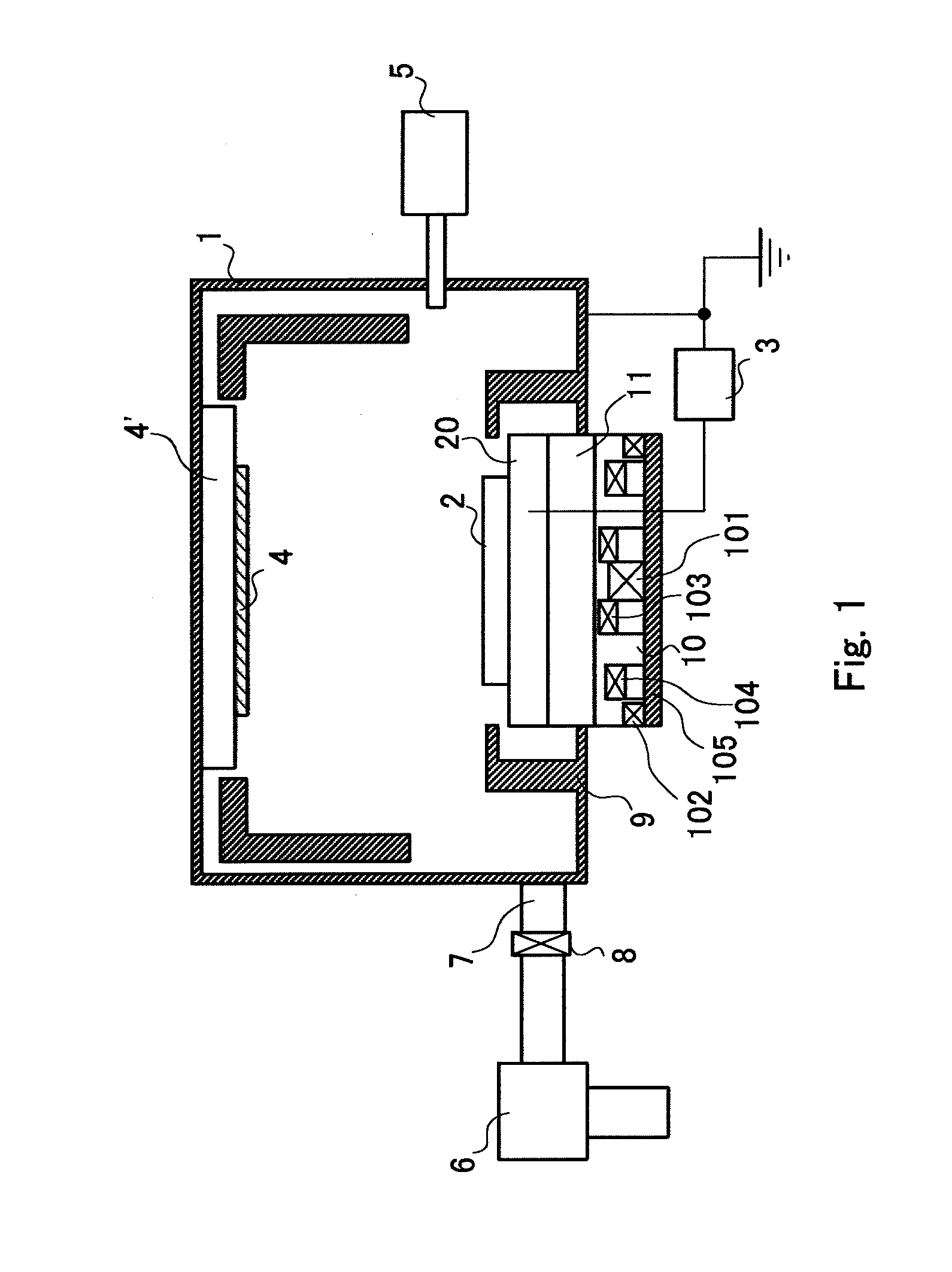
[0091]FIG. 1 is a schematic view of a sputtering apparatus of Embodiment 1 according to the present invention. The sputtering apparatus shown in FIG. 1 includes vacuum chamber 1, a magnetron electrode containing target 2 and water-cooling jacket 11 and magnetic circuit 10, and substrate 4.

[0092]In vacuum chamber 1, gas introduction apparatus 5, exhauster 6, exhaust port 7, and valve 8 are provided. Exhauster 6 carries out negative pressure in the inside of vacuum chamber 1. Gas introduction apparatus 5 introduces sputtering gas into the inside of vacuum chamber 1. Sputtering gas is generally inactive gas such as Ar gas and the like.

[0093]The magnetron electrode has target 2 composed of a film material, high voltage impression power supply 3 connected to target 2, and magnetic circuit 10 arranged on the back surface (surface opposite to the surface where substrate 4 is arranged) side of target 2. Water-cooling jacket 11 is arranged between magnetic circuit 10 and target 2. In additio...

embodiment 2

[0101]FIG. 8 is a schematic view of a sputtering apparatus of Embodiment 2 according to the present invention. In FIG. 8, the same numerals are given to the same components as in FIG. 1, and the repeated explanations thereof are omitted herein.

[0102]In the sputtering apparatus shown in FIG. 8, water-cooling jacket 11 is arranged between target 2 and magnetic circuit 10 in the same manner as in Embodiment 1. Concave space 12 is arranged in the magnetic circuit side of water-cooling jacket 11. Inside parallel magnet 103 enters concave space 12, and interval D1 between magnet 103 and the surface of target 2 is shrunk.

[0103]Since portions other than concave space 12 of water-cooling jacket 11 are kept thicker than the portion of space 12, the flow of cooling water is easily secured.

[0104]In the sputtering apparatus of Embodiment 2, for example, the thickness of target 2 is 5 mm, and the thickness of packing plate 20 is 10 mm. And more, the thickness of the portion of water-cooling jacke...

embodiment 3

[0106]FIG. 9A and FIG. 9B are schematic views of a magnetron electrode (only magnetic circuit 10 and water-cooling jacket 11) of a sputtering apparatus of Embodiment 3 according to the present invention. FIG. 9A is a cross sectional view of water-cooling jacket 11, and FIG. 9B is a top view of water-cooling jacket 11 when seen from the normal line direction of the back surface of the target. In FIG. 9A and FIG. 9B, the same numerals are given to the same components as in FIG. 1, and the repeated explanations thereof are omitted herein.

[0107]In the sputtering apparatus of Embodiment 3, in the same manner as in the sputtering apparatus of Embodiment 2, concave space 12 is arranged in part of water-cooling jacket 11, in order to shrink interval D1 between magnet 103 and the surface of target 2 (refer to FIG. 9A). Further, concave space 12 formed in water-cooling jacket 11 is divided into plural spaces by slits 14 (FIG. 9B). In other words, magnet 103 is also divided, provided in respec...


PUM

PropertyMeasurementUnit
crossing angleaaaaaaaaaa
thicknessaaaaaaaaaa

Abstract

The present invention is to provide a sputtering apparatus and a sputtering method, specifically, a magnetron sputtering apparatus having a magnetron electrode capable of generating plasma in a wide region near the surface of a target, and a sputtering method using the apparatus. Thereby, a magnetic field shape enabling to generate plasma in a wide region near the surface of a target is realized, the use efficiency of the target material is increased, and dusts and abnormal electric discharges may be prevented. Magnetic circuit 10 of a magnetron electrode is set as “magnetic circuit 10 in which center perpendicular magnet 101, inside parallel magnet 103, outside parallel magnet 104, and perimeter perpendicular magnet 102 are arranged” from the central part of target 2 toward the perimeter part, and inside parallel magnet 103 is brought close to target 2.

Description

CROSS REFERENCE TO RELATED APPLICATIONS[0001]This application claims foreign priorities based on application number JP2007-309768 filed on Nov. 30, 2007, and JP2008-221602 filed on Aug. 29, 2008. The entire content disclosed in the specification, drawings and abstracts of the aforementioned applications is incorporated herein by reference in its entirety.BACKGROUND OF THE INVENTION[0002]1. Field of the Invention[0003]The present invention relates to a sputtering apparatus and a sputtering method.[0004]2. Description of the Related Art[0005]Sputtering is a technology in which a substrate and a target (a member to become the raw material of a sputtering film) are arranged in vacuum, and plasma is generated in the vacuum and a film is formed on the substrate. According to the sputtering using plasma, because sputtered particles of high energy reach the substrate, adhesion of the sputtered particles with the substrate becomes high. Therefore, the sputtering using plasma has an advantage...

Claims


Application Information

Patent Timeline
Patent Type & Authority Applications(United States)
IPC IPC(8): C23C14/35
CPCC23C14/35H01J37/3452H01J37/3408
Inventor YAMAMOTO, MASAHIROKOIWASAKI, TAKESHIMURAGISHI, ISAOYAMANISHI, HITOSHI
Owner PANASONIC CORP
Why Eureka
Try Eureka