Methods and devices for treatment of bone fractures

a bone fracture and bone marrow technology, applied in the field of bone fracture treatment, can solve the problems of permanent misalignment of the healed bone, bone is not stabilized, and may occur, and achieve the effects of preserving the majority of bone marrow volume, preserving a large quantity of bone marrow cavity, and low surface area and mass

Inactive Publication Date: 2009-06-04
MISCHE HANS A
View PDF4 Cites 37 Cited by
  • Summary
  • Abstract
  • Description
  • Claims
  • Application Information

AI Technical Summary

Benefits of technology

[0007]In contrast to the prior art, embodiments of the present invention propose treatment of bone fractures using minimally invasive techniques, methods, equipment and devices to position and deliver an expandable fracture fixating device into the medullary cavity (marrow conduit). The device is preferably an expandable structure that “bridges” the fracture site and fixates the site upon expansion. In addition to fixation, the device also joins the fractured bone such as in the case of a compound fracture. Referring to the device as a bridge, the BRIDGE is substantially hollow and has low surface area and mass, the majority of bone marrow volume can be preserved. The ability to preserve a large quantity of the bone marrow cavity is beneficial for healing, bone health and maintaining the body's natural ability to generate red blood cells. In addition, the stress applied to the bone by the expanded or expanding “BRIDGE” facilitates rapid bone growth and strength. The operable level of stress applied to the bone will vary from low levels to high levels dependent on the type, size and location of bone to be treated. It is also envisioned that the BRIDGE can be used to expand and support bones that are crushed or compressed. The BRIDGE can be delivered by a variety of expansion devices, can be self expanding to due to inherent spring forces within the BRIDGE structure, or can be expansively actuated utilizing elements and mechanisms within the BRIDGE structure. These various devices and alternative embodiments will be detailed further.

Problems solved by technology

With the use of casts, the bone is not stabilized and misalignment may occur after placing the cast.
This is a very uncomfortable and painful procedure for the victim or patient and can ultimately result in permanent misalignment of the healed bone.
The treatment modalities requiring a surgical procedure are painfull and are associated with a high rate of complications.
Post-procedural infections are one of the major complications associated with these surgical procedures.
Many of these infections result in necrosis of bone and tissue and require additional surgical interventions and therapy.

Method used


Image

  • Methods and devices for treatment of bone fractures
  • Methods and devices for treatment of bone fractures
  • Methods and devices for treatment of bone fractures

Examples


Embodiment Construction

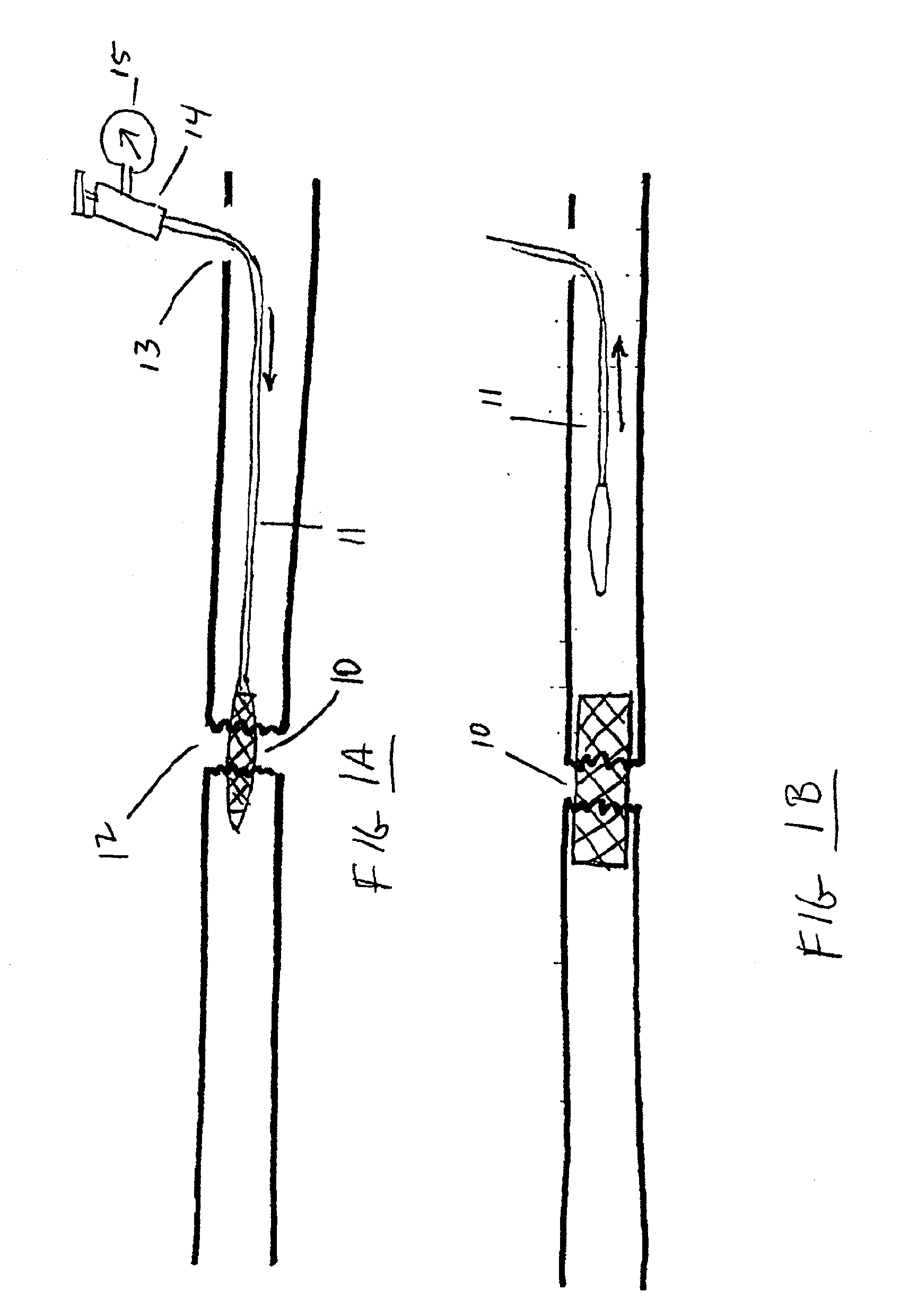
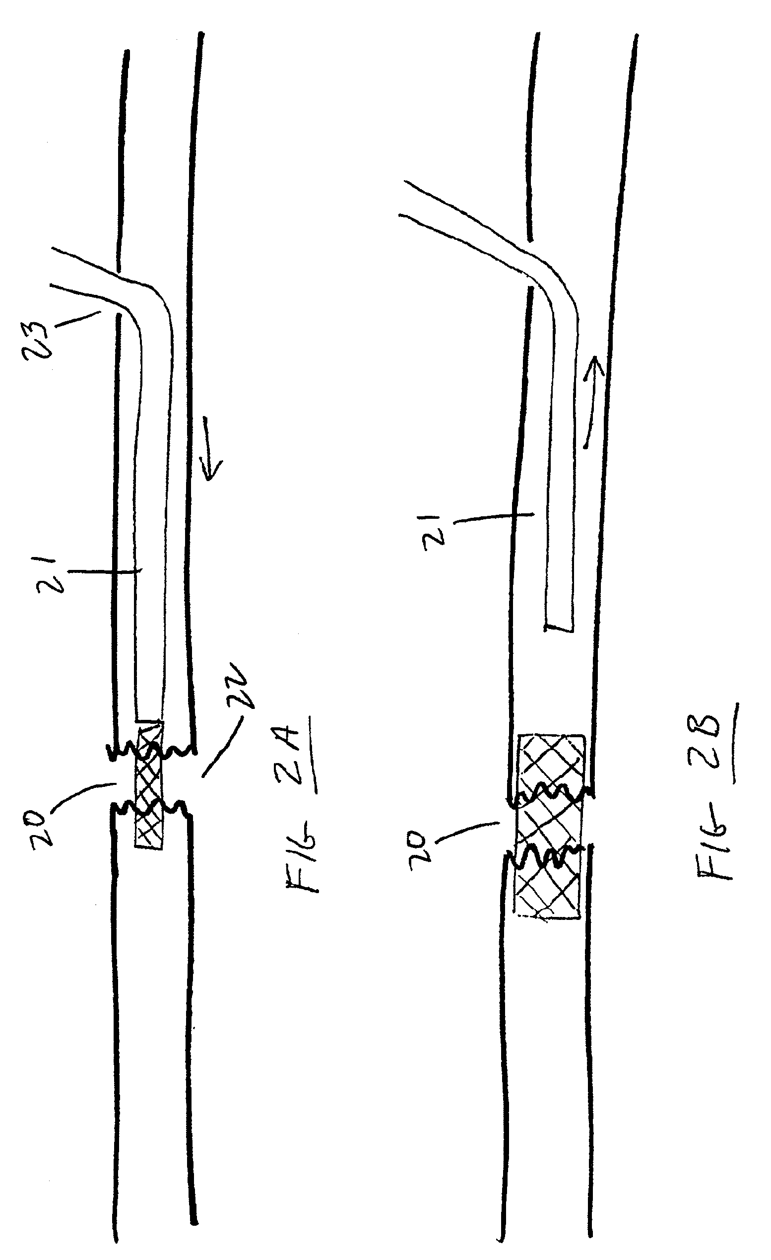
[0032]Throughout the description the term BRIDGE refers to an expandable device that is used to fixate or repair bone fractures. The device may be made of metals such as stainless steel, tantalum, titanium, Nitinol or Elgiloy and it may form an electrode for electrical stimulation. One or more electrodes may be associated with it. The BRIDGE may incorporate fiber optics for imaging, sensing, or the transmission of energy to heat, ablate, illuminate, or as one skilled in the art would understand, cure therapeutic materials such as polymers and adhesive. The device may also be made from a plastic or other non-metallic material. The BRIDGE may also incorporate a covering of polymer or other materials. The BRIDGE may also be a composition of different materials. The BRIDGE may be smooth or have cutting or abrasive surfaces. The BRIDGE can be self-expanding or use a device such as a balloon catheter to mechanically expand or further expand it. In addition, other means of expanding the BR...


PUM


Abstract

A method and devices for facilitating fixating and joining of bone fractures utilizing expandable devices that are positioned within the bone and across the fracture site. The stress from the expanded devices may enhance and expedite bone healing.

Description

CROSS-REFERENCE TO RELATED APPLICATIONS[0001]This application claims the benefit of priority to U.S. Provisional No. 60 / 982,931, filed on Oct. 26, 2007, which is incorporated by reference in its entirety herein.[0002]This application claims the benefit as a continuation-in-part of priority from U.S. application Ser. No. 09 / 733,775, filed Dec. 8, 2000, which claims priority to U.S. Provisional Nos. 60 / 169,778, filed Dec. 9, 1999, 60 / 181,651, filed Feb. 10, 2000, and 60 / 191,664, filed Mar. 23, 2000, all of which are incorporated by reference in their entireties herein.BACKGROUND OF THE INVENTION[0003]1. Field of the Invention[0004]Embodiments of the present invention relate generally to the treatment of bone fractures utilizing expandable fracture fixating devices within the medullary cavity of bones, and equipment and methods specially designed for implanting these devices. Novel methods and devices for the treatment of bone fractures are disclosed.[0005]2. Description of the Related...

Claims


Application Information

Patent Timeline
Patent Type & Authority Applications(United States)
IPC IPC(8): A61B17/58
CPCA61B17/7225A61N1/326A61B17/7275A61B17/80A61B17/8858A61B18/02A61B18/04A61B18/20A61B2017/00539A61B2017/00544A61B2017/00557A61B2017/00867A61F2002/2821A61M25/10A61M25/104A61M2025/1068A61M2210/02A61B17/7258
Inventor MISCHE, HANS A.
Owner MISCHE HANS A
Why Eureka
Try Eureka