Driver circuit

a technology of driving circuit and drive circuit, which is applied in the direction of oscillator generator, pulse technique, electronic switching, etc., can solve the problems of thermally severe environment of the driving circuit positioned in the vicinity of the insulated gate power device, increase manufacturing cost, and many man-hours for the gate drive design, so as to reduce losses and noise, improve the driving performance of the insulated gate device, and optimize the gate voltage waveform

Active Publication Date: 2009-06-11
FUJI ELECTRIC CO LTD
View PDF9 Cites 11 Cited by
  • Summary
  • Abstract
  • Description
  • Claims
  • Application Information

AI Technical Summary

Benefits of technology

[0016]The driver circuit, which adjusts the gate voltage waveform outputted from the slope setting circuit as described above, makes it possible to adjust the gate voltage waveform of the insulated gate device and to drive the gate of the insulated gate device with a high driving capability or with a reduced driving capability in the respective stages of the turn-on. Therefore, the driver circuit according to the invention facilitates reducing the losses and noises caused by driving the insulated gate device and improving the driving performances thereof without connecting a series circuit of a resistor and a capacitor to the gate of the insulated gate device. In addition, the driver circuit according to the invention facilitates reducing the number of the component parts, preventing the substrate area from being widened and reducing the manufacturing costs thereof.
[0037]The driver circuit according to the invention makes it possible to reduce losses and noises and to improve the driving performances thereof without using a series circuit of a capacitor and a resistor connected to the gate of the insulate gate device. The driver circuit according to the invention makes it possible to reduce the number of the component parts, to prevent the substrate area from being widened, and to reduce the manufacturing costs thereof.

Problems solved by technology

Therefore, when an insulated gate power device and the driver circuit thereof are mounted on the common module, the driver circuit positioned in the vicinity of the insulated gate power device is in a thermally severe environment.
Therefore, many man-hours are necessary for the gate drive design.
Therefore, the number of component parts and the substrate area are increased, further causing manufacturing cost increase.

Method used


Image

  • Driver circuit
  • Driver circuit
  • Driver circuit

Examples


Embodiment Construction

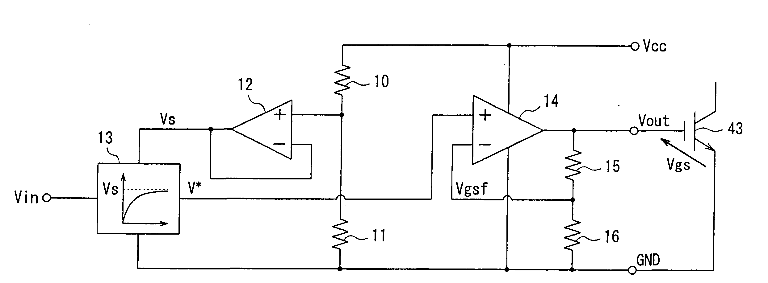
[0045]FIG. 1 is a block circuit diagram describing the configuration of a driver circuit according to a first embodiment of the invention. As shown in FIG. 1, a driver circuit according to a first embodiment includes slope setting circuit 13 that sets the gate voltage waveform of IGBT 43. Slope setting circuit 13 is triggered by a trigger input to output a gate voltage waveform, on which the gate voltage increases exponentially or linearly.

[0046]The power supply terminal of slope setting circuit 13 is connected to the output terminal of operational amplifier 12. The ground terminal of slope setting circuit 13 is connected to the ground potential GND. The output terminal of slope setting circuit 13 is connected to the non-inverting input terminal of operational amplifier 14.

[0047]Resistor 10 and resistor 11 are connected in series to each other between the power supply voltage Vcc of the driver circuit and the ground potential GND. The non-inverting input terminal of operational ampl...


PUM


Abstract

A driver circuit facilitates reducing noises and losses and improving the driving performances thereof without connecting a series circuit of capacitor and a resistor to the gate of IGBT. The driver circuit includes a slope setting circuit that sets the gate voltage waveform of IGBT; and an operational amplifier that includes a non-inverting input terminal, to which an output voltage V* from slope setting circuit is inputted, and an inverting input terminal, to which a divided voltage Vgsf divided by resistors is inputted; and the operational amplifier outputs an output voltage Vout, proportional to the difference between the output voltage V* and the divided voltage Vgsf, to the gate of IGBT.

Description

BACKGROUND[0001]The present invention relates to a driver circuit. Specifically, the invention relates to a driver circuit that is preferably applicable for reducing the losses and noises of an insulated gate power device and for improving the driving performances thereof.[0002]In semiconductor electric power converters, insulated gate power devices such as an insulated gate bipolar transistor (hereinafter referred to as an “IGBT”) and a power MOSFET are used. Some conventional driver circuits for driving the insulated gate power devices are formed of an inverter.[0003]FIG. 6, for example, is a circuit diagram briefly describing the structure of a conventional driver circuit. In FIG. 6, the conventional driver circuit includes P-channel field-effect transistor 41 and N-channel field-effect transistor 42 connected in series to each other. The source of P-channel field-effect transistor 41 is connected to a power supply voltage Vcc. The source of N-channel field-effect transistor 42 i...

Claims


Application Information

Patent Timeline
Patent Type & Authority Applications(United States)
IPC IPC(8): H03K5/12
CPCH03K17/163H03K2217/0036H03K17/168
Inventor NAKAMORI, AKIRAMORI, TAKAHIROYAMAZAKI, TOMOYUKI
Owner FUJI ELECTRIC CO LTD
Why Eureka
Try Eureka