
Microwave demulsification of hydrocarbon emulsion

a technology of hydrocarbon emulsion and microwave energy, applied in the direction of slot antenna, antenna details, antennas, etc., can solve the problems of reducing the pumping power involved in extracting petroleum products, limiting the effectiveness of those approaches, and microwave energy often does not penetrate sufficiently deeply to treat the entire emulsion

Inactive Publication Date: 2009-06-11
INTEGRITY DEV
View PDF67 Cites 6 Cited by
  • Summary
  • Abstract
  • Description
  • Claims
  • Application Information

AI Technical Summary

Benefits of technology

The solution enables more effective demulsification with reduced energy waste and heat generation, allowing for higher microwave energy use and improved efficiency in hydrocarbon recovery, while minimizing the risk of ignition and energy costs.

Problems solved by technology

As a result, the viscosity of the hydrocarbons is lowered, which in turn reduces the pumping power involved in extracting the petroleum products.
While microwave treatment of emulsions can separate the emulsions to some degree, certain drawbacks of some conventional approaches limit the effectiveness of those approaches.
Further, in approaches in which microwave energy is emitted from a source above the emulsion, the microwave energy often does not penetrate adequately deeply to treat the entire emulsion.
Only a portion of the emulsion, such as a surface layer, is heated effectively, potentially resulting in inefficient demulsification.
Even in approaches in which microwave energy is applied via an antenna inserted in a borehole, many antennas do not radiate the microwave energy effectively.
As a result, such antennas typically consume relatively large amounts of power, leading to high costs.
In addition, a substantial portion of the microwave energy not radiated is internally reflected within the antenna, potentially resulting in heating of the antenna itself and an elevated risk of combustion as described above.

Method used


Image

  • Microwave demulsification of hydrocarbon emulsion
  • Microwave demulsification of hydrocarbon emulsion
  • Microwave demulsification of hydrocarbon emulsion

Examples


Embodiment Construction

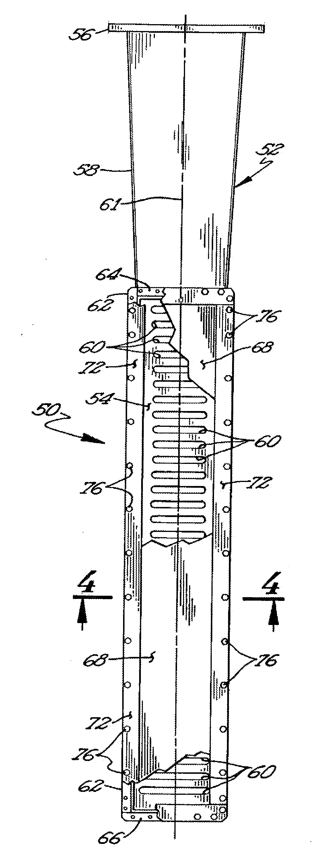
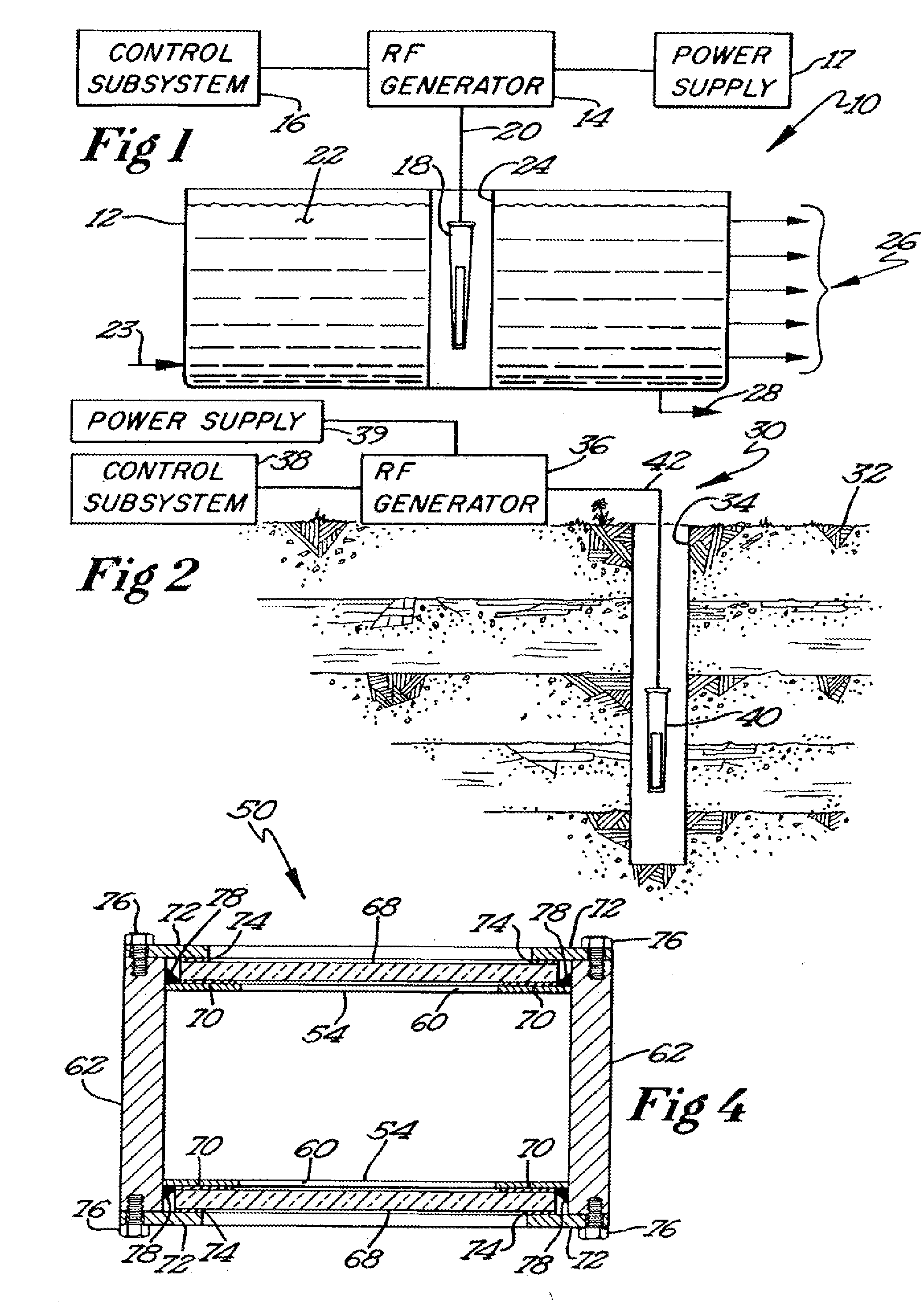
[0022]Various embodiments of a demulsification system facilitate recovery of hydrocarbons, such as petroleum products, from a liquid or solid substrate by using microwave energy to energize and separate molecular bonds between the hydrocarbons and the substrate. A microwave applicator delivers microwave energy to a treatment volume containing an emulsion of a hydrocarbon and a substrate. Delivering the microwave energy to the emulsion imparts energy to electrons and molecular bonds between the hydrocarbon and the substrate. As a result, the hydrocarbon and substrate molecules separate into strata or layers. Hydrocarbons and other products can then be recovered from their respective layers. The treatment volume may be located either above or below ground. For example, the treatment volume may be a treatment tank or a medium located near a down hole or bore hole, such as a geologic formation containing oil shale, tar sand, or ground water contamination.

[0023]In one implementation, a r...


PUM


Abstract

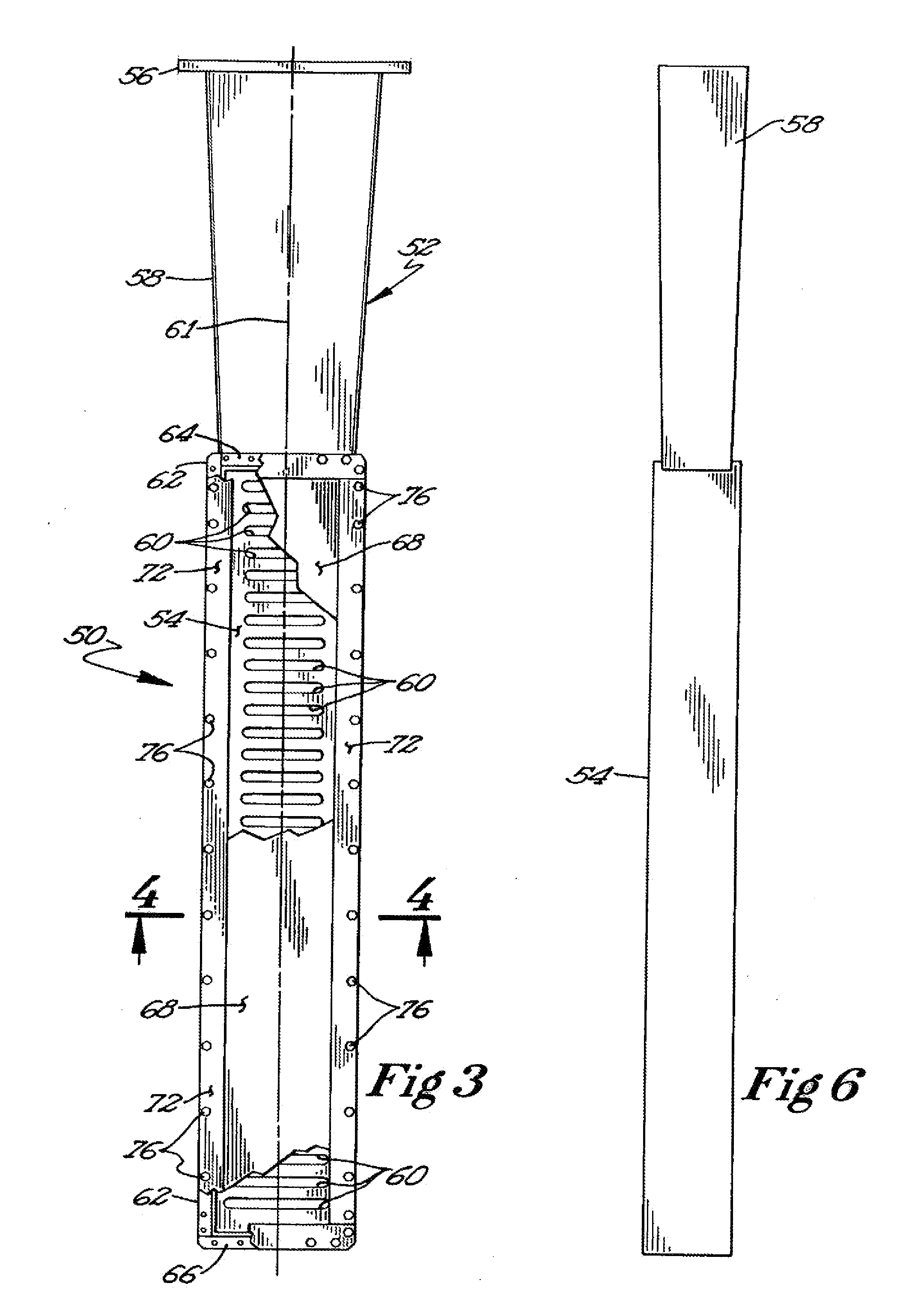
Recovery of hydrocarbons, such as petroleum products, from a liquid or solid substrate is facilitated by the use of microwave energy to energize and separate molecular bonds between the hydrocarbons and the substrate. A radio frequency (RF) applicator delivers microwave energy to a treatment volume containing an emulsion of a hydrocarbon and a substrate. Delivering the microwave energy to the emulsion facilitates separation of the hydrocarbon and substrate molecules into layers. Hydrocarbons and other products can then be recovered from their respective layers. The treatment volume may be located either above or below ground. The RF applicator may include an antenna body with slots formed substantially parallel to one another in a substantially horizontal orientation. The RF applicator efficiently delivers microwave energy into the treatment volume. Substantially all of the power supplied to the RF applicator is radiated, with very little power reflected internally within the RF applicator.

Description

RELATED APPLICATIONS[0001]This application is a divisional of U.S. Ser. No. 10 / 619,011, filed Jul. 14, 2003.FIELD OF THE INVENTION[0002]The invention relates generally to hydrocarbon recovery techniques. More particularly, the invention relates to hydrocarbon recovery via application of microwave energy.BACKGROUND OF THE INVENTION[0003]Hydrocarbons, such as petroleum products, have been recovered from underground media, such as oil shale, tar sand, and ground water contamination, using a variety of techniques, including heat and chemical treatment. As is well known in the art, heating the petroleum products reduces their viscosity, facilitating extraction from the medium. Various techniques have been proposed for heating the petroleum products. For instance, a geologic formation can be heated via electrodes deployed in the ground using resistance heating. As an alternative, the geologic formation can be heated by steam that is either delivered to the geologic formation or formed wit...

Claims


Application Information

Patent Timeline
Patent Type & Authority Applications(United States)
IPC IPC(8): H01Q13/10H01Q1/04H01Q13/12
CPCH01Q13/12H01Q1/04
Inventor HALEK, JAMES MICHAELHARRIS, PHILIP AARONTHOMPSON, RICHARDFERRI, ROBERTSQUIRES, JONATHAN
Owner INTEGRITY DEV
Learn More