
Maximum likelihood sequence estimation decoding

a technology of sequence estimation and probability, applied in the direction of amplitude demodulation, digital signal error detection/correction, instruments, etc., can solve the problems of limiting an even wider acceptance of the algorithm, large processing power and computational resources, so as to achieve efficient interference reduction, reduce complexity, and high performance

Inactive Publication Date: 2009-06-11
KONINKLIJKE PHILIPS ELECTRONICS NV
View PDF14 Cites 4 Cited by
  • Summary
  • Abstract
  • Description
  • Claims
  • Application Information

AI Technical Summary

Benefits of technology

[0011]The invention may improve the performance of a Maximum Likelihood Sequence Estimator and may specifically improve data detection reliability. The invention may reduce the complexity of a Maximum Likelihood Sequence Estimator and / or may reduce the computational resource requirement. The invention may reduce hardware requirements and / or reduce cost for a Maximum Likelihood Sequence Estimator.
[0029]This may allow a practical, efficient implementation and / or high performance. In particular, it may allow the complexity of the pre-compensation to be kept low while allowing efficient performance. Specifically, the invention may allow a simple detection means to be used for mitigating intersymbol interference outside the Maximum Likelihood Sequence Estimation window without significant degradation impact (e.g. due to detection errors) on the intersymbol interference mitigation by the Maximum Likelihood Sequence Estimation.

Problems solved by technology

However, the Viterbi algorithm is relatively complex and requires large amounts of processing power and computational resource.
Indeed, the associated hardware cost is one of the factors that currently limit an even wider acceptance of the algorithm in optical disc storage systems.
Accordingly, current approaches inherently require a trade-off between performance and complexity (e.g. computational complexity and / or hardware cost) and in practical systems the data detection performance accordingly tends to have a higher error rate than theoretically achievable.

Method used


Image

  • Maximum likelihood sequence estimation decoding
  • Maximum likelihood sequence estimation decoding
  • Maximum likelihood sequence estimation decoding

Examples


Embodiment Construction

[0041]The following description focuses on embodiments of the invention applicable to an optical disc reading system using a Maximum Likelihood Sequence Estimator for data detection. However, it will be appreciated that the invention is not limited to this application but may be applied to many other decoding systems including for example decoders for communication systems.

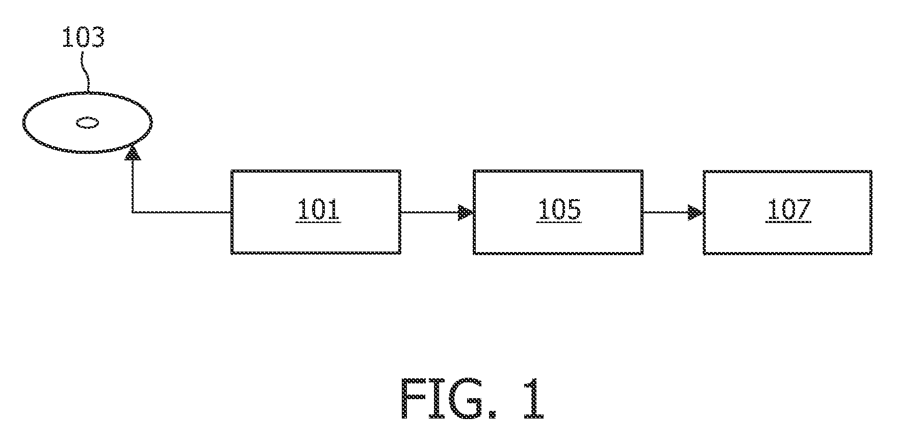
[0042]FIG. 1 illustrates an example of an optical disc reading apparatus in accordance with some embodiments of the invention.

[0043]In the example, an optical disc data reader 101 reads data from an optical disc 103. The data stored on the optical disc 101 is RLL (Run Length Limited) coded. The data samples read from the optical disc are fed from the optical disc data reader 101 to a Maximum Likelihood Sequence Estimator which specifically is a Viterbi bit detector 105. The Viterbi bit detector 105 uses at the Viterbi algorithm to determine the data values which are read from the optical disc 103. The detected dat...


PUM


Abstract

A Maximum Likelihood Sequence Estimator comprises a signal receiver (401) which receives a first signal for decoding. An ISI processor (403) generates a compensation signal from the first signal. The compensation signal represents intersymbol interference outside a channel model window of a Maximum Likelihood Sequence Estimation (MLSE) but does not represent intersymbol interference within the channel model window of the MLSE. A compensation processor (405) generates a compensated signal by compensating the first signal by the compensation signal, e.g. by subtracting the compensation signal from the first signal. The compensated signal is fed to a MLSE decoder (407) which decodes data of the first signal by performing the MLSE on the compensated signal. The invention may provide reduced detection error rates and may in particular be suitable for optical disc reading systems.

Description

FIELD OF THE INVENTION[0001]The invention relates to Maximum Likelihood Sequence Estimation and in particular, but not exclusively, to Viterbi decoding for optical storage disc reading systems.BACKGROUND OF THE INVENTION[0002]Methods and techniques for detecting and correcting bit errors in data processing or distribution systems are widely known. For example, communication systems wherein data is communicated over an unreliable communication link typically employ forward error correction coding and decoding to reduce the amount of communication errors. As another example, optical disc reading systems tend to employ error decoding in order to reduce the amount of reading errors.[0003]A particularly efficient technique for detecting correct bit values in the presence of bit errors is known as Maximum Likelihood Sequence Estimation and specifically Partial Response Maximum Likelihood (PRML) bit detection. In particular, the Viterbi algorithm is commonly used for communication systems ...

Claims


Application Information

Patent Timeline
IPC IPC(8): G11B20/10G11B7/005G11B7/00H03M13/41
CPCH03M13/00G11B20/18G11B20/10G11B20/14
Inventor VLUTTERS, RUUD
Owner KONINKLIJKE PHILIPS ELECTRONICS NV
Learn More