Demultiplexer and communication device

a communication device and multi-layer technology, applied in the field of duplexers, can solve the problems of insufficient miniaturization, insufficient height reduction and miniaturization, and the inability of duplexers manufactured using csp technology to use bonding wires having inductance components, etc., to achieve the effect of improving an attenuation characteristic and an isolation characteristi

a communication device and multi-layer technology, applied in the field of duplexers, can solve the problems of insufficient miniaturization, insufficient height reduction and miniaturization, and the inability of duplexers manufactured using csp technology to use bonding wires having inductance components, etc., to achieve the effect of improving an attenuation characteristic and an isolation characteristi

US20090147707A1Active Publication Date: 2009-06-11KYOCERA CORP

Image

  • Demultiplexer and communication device
  • Demultiplexer and communication device
  • Demultiplexer and communication device

Examples


example

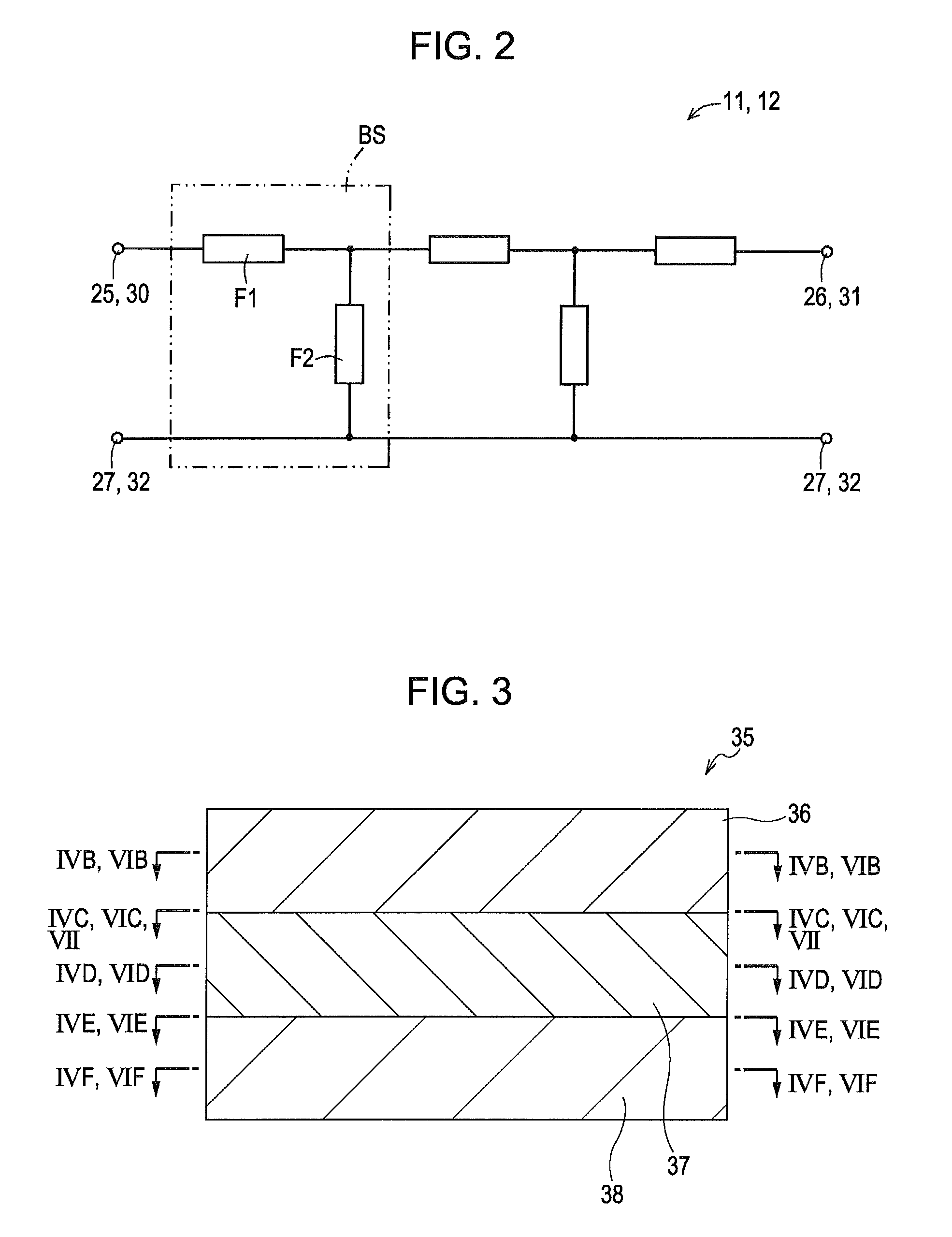
[0096]An example of the duplexer 10 and a comparative example will now be described below. Three-layered LTCC is used as a material of the mounting substrate 35 constituting the duplexer 10. The LTCC is mainly made of alumina and has a relative dielectric constant of 9.4. A thickness of one layer of the LTCC is equal to 0.125 mm. Electrodes made of silver are formed on surfaces of each layer. The smallest width of the electrodes is equal to 0.075 mm. In addition, a diameter of a via that connects the electrodes formed on the surfaces of the layers is equal to 0.1 mm. The via is filled with silver.

[0097]To constitute a duplexer of 800 MHz, a filter having a passband between 824 MHz and 849 MHz and a filter having a passband between 869 MHz and 894 MHz are used as a transmission filter and a reception filter, respectively.

[0098]In this example, a SAW device was formed using a thin film process. Referring to FIG. 8, single crystal of lithium tantalate (LiTaO3) was used as a piezoelectr...


PUM


Abstract

Provided is a demultiplexer capable of improving attenuation characteristic and isolation characteristic of a filter having a lower transmission frequency band among two filters having different transmission frequency bands, outside the transmission frequency band of a high-frequency side. A communication device using the demultiplexer is also disclosed. A first spiral wiring portion (55) and a sixth wiring portion (56) are formed so that an angle defined by a direction of a part (L1) of the first spiral wiring portion (55) and a direction of a part (L2) of the sixth spiral wiring portion (56) on a predetermined virtual plane is, for >example, 0 degree and the direction of the current flowing in the part (L1) of the first spiral wiring portion (55) is opposite to the direction of the current flowing in the part (L2) if the sixth wiring portion (56).

Description

TECHNICAL FIELD[0001]The present invention relates to a duplexer including a plurality of filters having different passbands and to a communication device including the same.BACKGROUND ART[0002]Regarding filters for use in mobile communication terminals, miniaturization and weight reduction are desired. Furthermore, it is desired that the filters have a small loss at a passband and large attenuation at a frequency band outside of the passband (hereinafter, referred to as a non-passband frequency band) and have a sharp frequency-characteristic change at a boundary between the passband and the non-passband frequency band.[0003]In addition, regarding duplexers that separate signals of a transmission frequency band from signals of a reception frequency band, miniaturization and weight reduction are desired. Transmission filters used in the duplexers are desired to have a low loss at a transmission frequency band and large attenuation at a reception frequency band and to have a sharp fre...

Claims


Application Information

Patent Timeline
11 Jun 2009
Publication
US20090147707A1
IPC
H04B1/44
CPC
H01P1/213; H04B1/52; H04B1/0057; H03H9/725
Inventors
KOGA, WATARU; TAKENOSHITA, TAKESHI