
Houseless fan with rotating tip ring as silencer

a fan and silencer technology, applied in the direction of liquid fuel engines, marine propulsion, vessel construction, etc., can solve the problems of annoying the listener, every rotating fan emits noise, housing is a common source of fan noise, etc., to reduce the noise during the operation of the fan, reduce the noise, reduce the effect of noise reduction

Inactive Publication Date: 2009-06-11
MINEBEA CO LTD
View PDF14 Cites 5 Cited by
  • Summary
  • Abstract
  • Description
  • Claims
  • Application Information

AI Technical Summary

Benefits of technology

[0007]An advantage of the present invention is the elimination, minimization, or otherwise reduction of noise during operation of the fan, particularly tonal noise. An axial fan according to the present invention exhibits increased performance. An axial fan according to the present invention is cheaper to produce due to a reduced parts count; i.e., there is no housing. The tip ring prevents or otherwise reduces the occurrence of fan stall.
[0008]The invention provides a rotating tip ring attached to the tip of the blades of an axial fan impeller which replaces classical housing structures, and which acts as a silencer by eliminating noise created by rotation of the impeller, particularly tonal noise. To enhance performance, an embodiment of the tip ring is constructed as a circular-arc which starts upstream of the leading edge and which ends downstream of the trailing edge.

Problems solved by technology

The housing is a common source of fan noise in such designs.
Every rotating fan radiates noise.
Most of the acoustic energy reveals itself as frequencies or tones (referred to as “tonal noise”) which contain most of the acoustic power, and are thus annoying to the listener.

Method used


Image

  • Houseless fan with rotating tip ring as silencer
  • Houseless fan with rotating tip ring as silencer
  • Houseless fan with rotating tip ring as silencer

Examples


Embodiment Construction

[0016]The figures described below demonstrate the basic concept and an illustrative specific instantiation of the tip-ring structure of an impeller in accordance with the present invention.

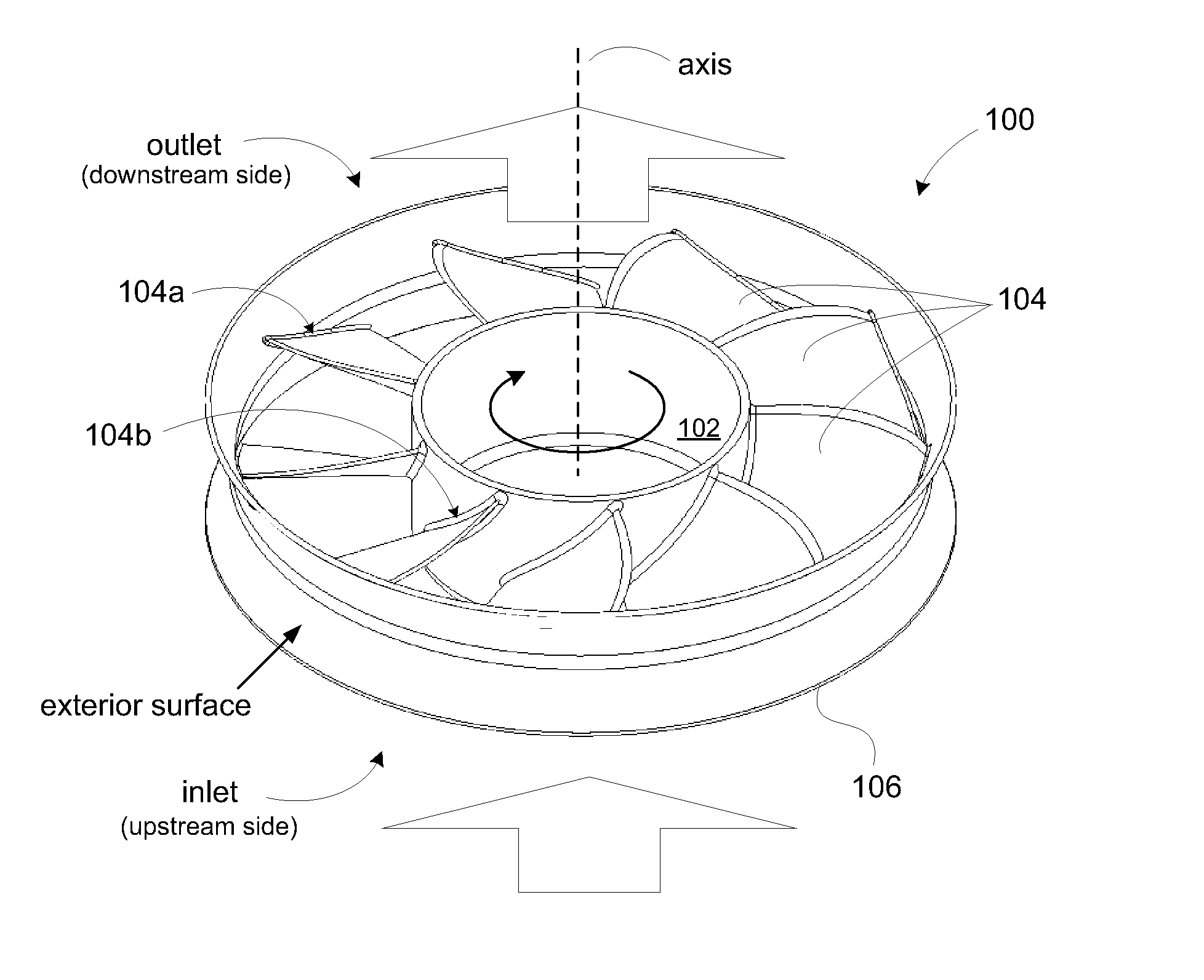
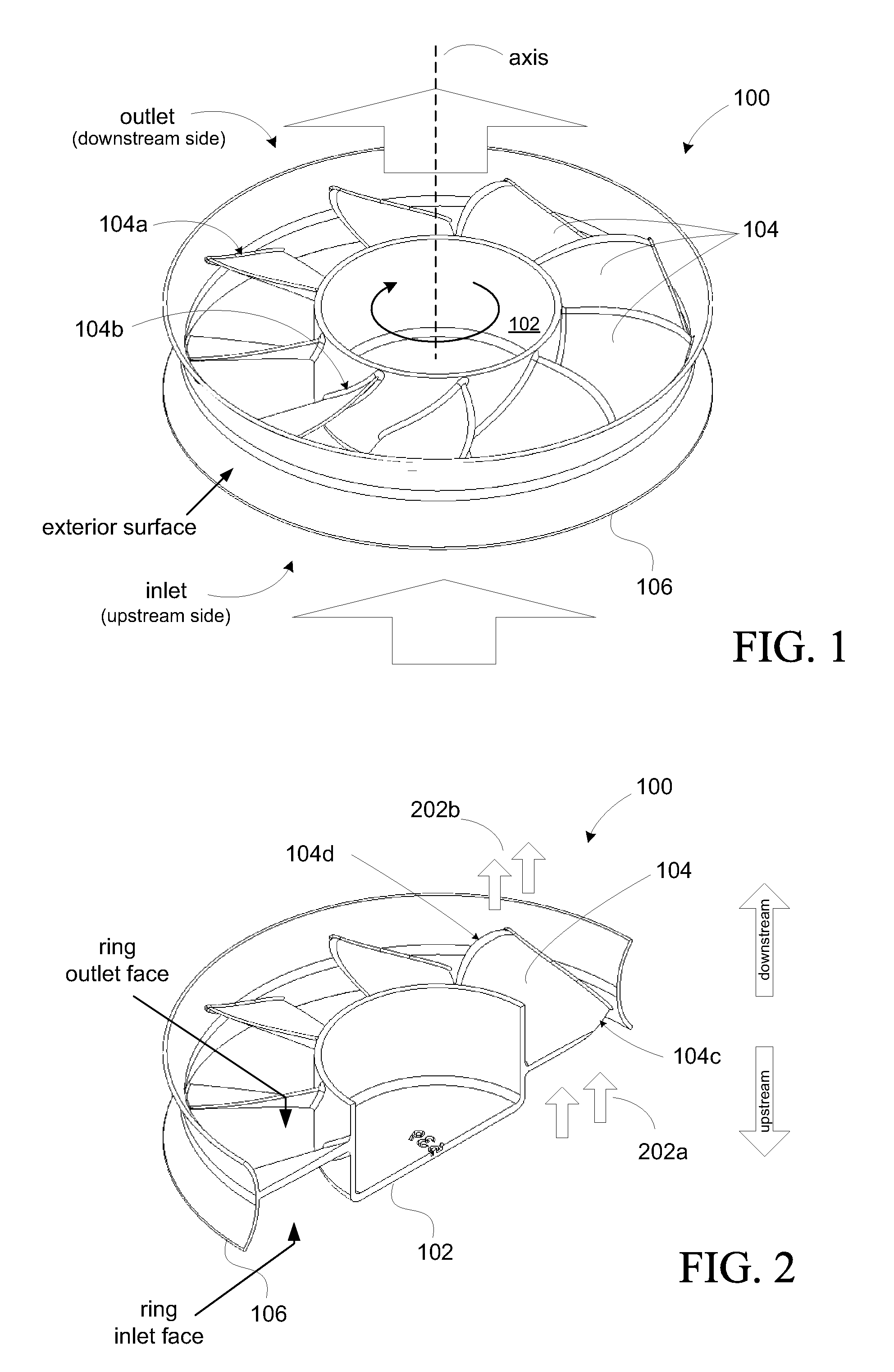
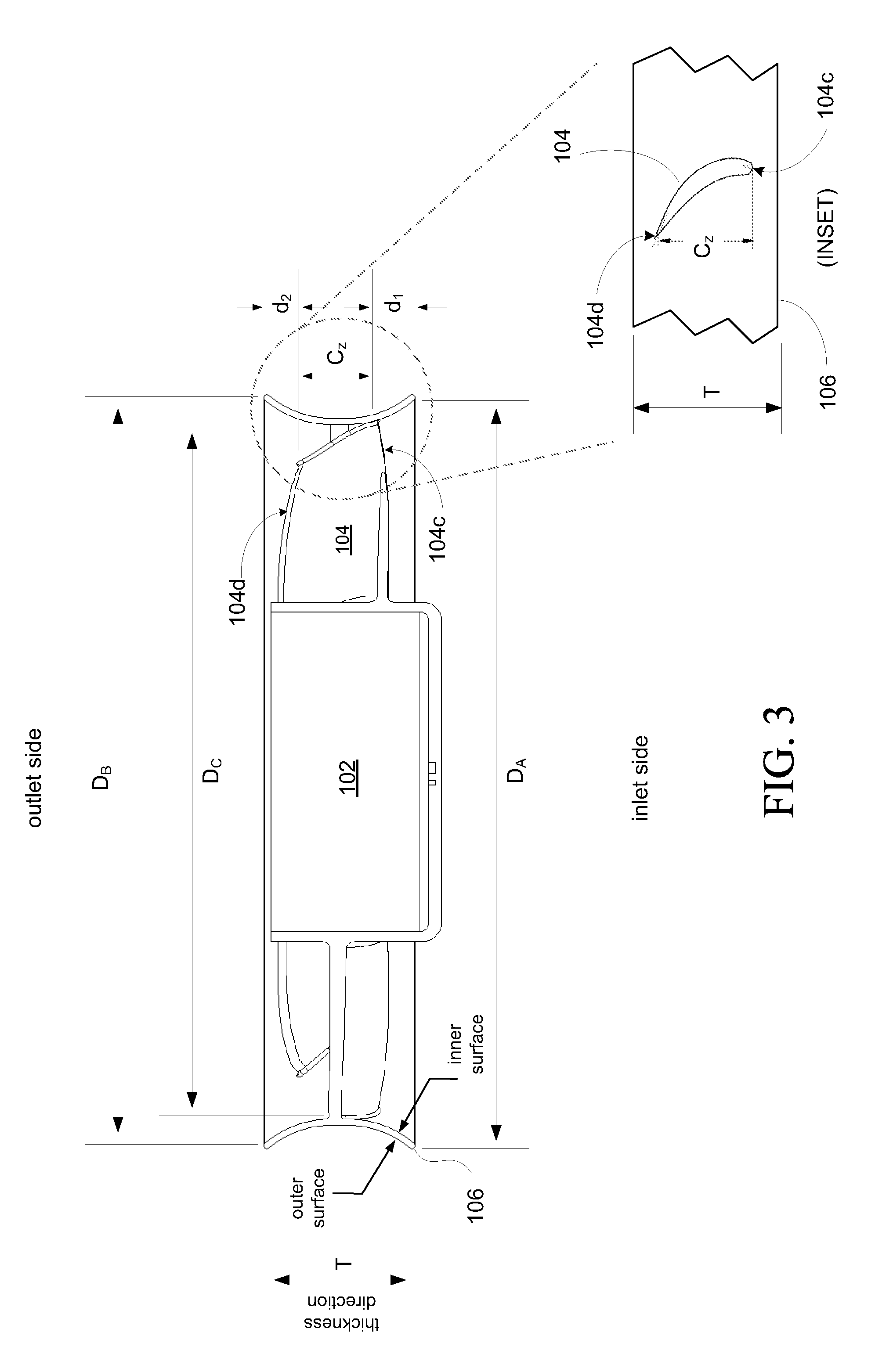
[0017]FIG. 1 is a perspective view of an embodiment of an impeller 100 for an axial flow fan according to the present invention. FIG. 2 shows a cross-sectional view of the impeller 100. The impeller 100 includes a hub 102 and a plurality of fan blades 104. The fan blades 104 are connected to the hub 102 at respective roots 104b of the fan blades. The figures illustrate an annular member 106 is disposed at respective tips 104a of the fan blades104. The annular member 106 is referred to herein variously as the ring, tip ring, band, etc.

[0018]The figures show that the tips 104a of the fan blades 104 are connected to the annular member 106. In other words, the annular member 106 is attached to the tips of the fan blades 104. This connection provides support for the fan blades 104 in addition to other ...


PUM


Abstract

The stationary housing of a conventional fan assembly is replaced with a rotating tip ring. The rotating tip ring has a shaped cross-sectional profile to enhance performance and eliminate tonal noise associated with the fundamental (or blade passing) frequency and its harmonics.

Description

BACKGROUND OF THE INVENTION[0001]The present invention relates generally to an axial flow fan and in particular to a fan impeller having improved noise characteristics.[0002]Conventional fans typically comprise a motor and an impeller coupled to the motor. The impeller includes a hub to which a set of fan blades are attached. The hub is connected to the rotor of the motor. Existing fan designs typically include a stationary housing to house the fan. The housing is a common source of fan noise in such designs.[0003]Every rotating fan radiates noise. Noise is function of a number of factors which include fan speed, size, and blade shape. Most of the acoustic energy reveals itself as frequencies or tones (referred to as “tonal noise”) which contain most of the acoustic power, and are thus annoying to the listener. These tonal modes are the harmonics; the first being the fundamental frequency (f, or the blade passing frequency), the second being 2f, the third is 3f, and so on. In other ...

Claims


Application Information

Patent Timeline
IPC IPC(8): F01D5/22
CPCF04D29/666F04D29/326
Inventor JARRAH, YOUSEF M.NGUYEN, THANG D.SITU, HANSON C.
Owner MINEBEA CO LTD
Learn More