Battery separator structures

a battery separator and structure technology, applied in the direction of cell components, final product manufacturing, sustainable manufacturing/processing, etc., can solve the problems of limiting battery performance in terms of capacity and discharge rate, consuming additional volume in the battery, and consuming electroly

Inactive Publication Date: 2009-06-11
GLATFELTER CORP
View PDF8 Cites 35 Cited by
  • Summary
  • Abstract
  • Description
  • Claims
  • Application Information

AI Technical Summary

Problems solved by technology

The pasting paper (if present) typically degrades over time due to contact with the electrolyte.
This consumes additional volume in the battery and displaces electrolyte.
This limits battery performance in terms of capacity and discharge rate, due to the lower amount of sulfuric acid available for ion exchang...

Method used


Image

  • Battery separator structures
  • Battery separator structures
  • Battery separator structures

Examples


Embodiment Construction

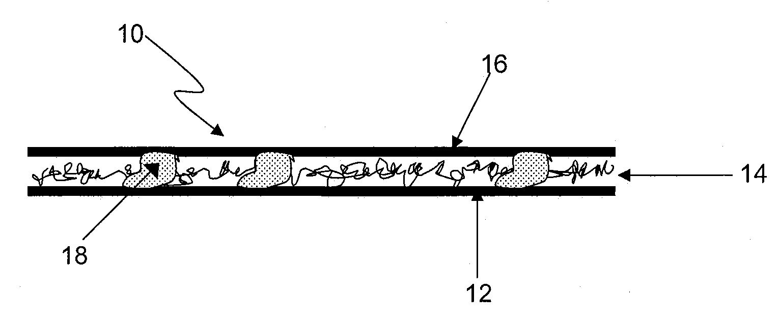
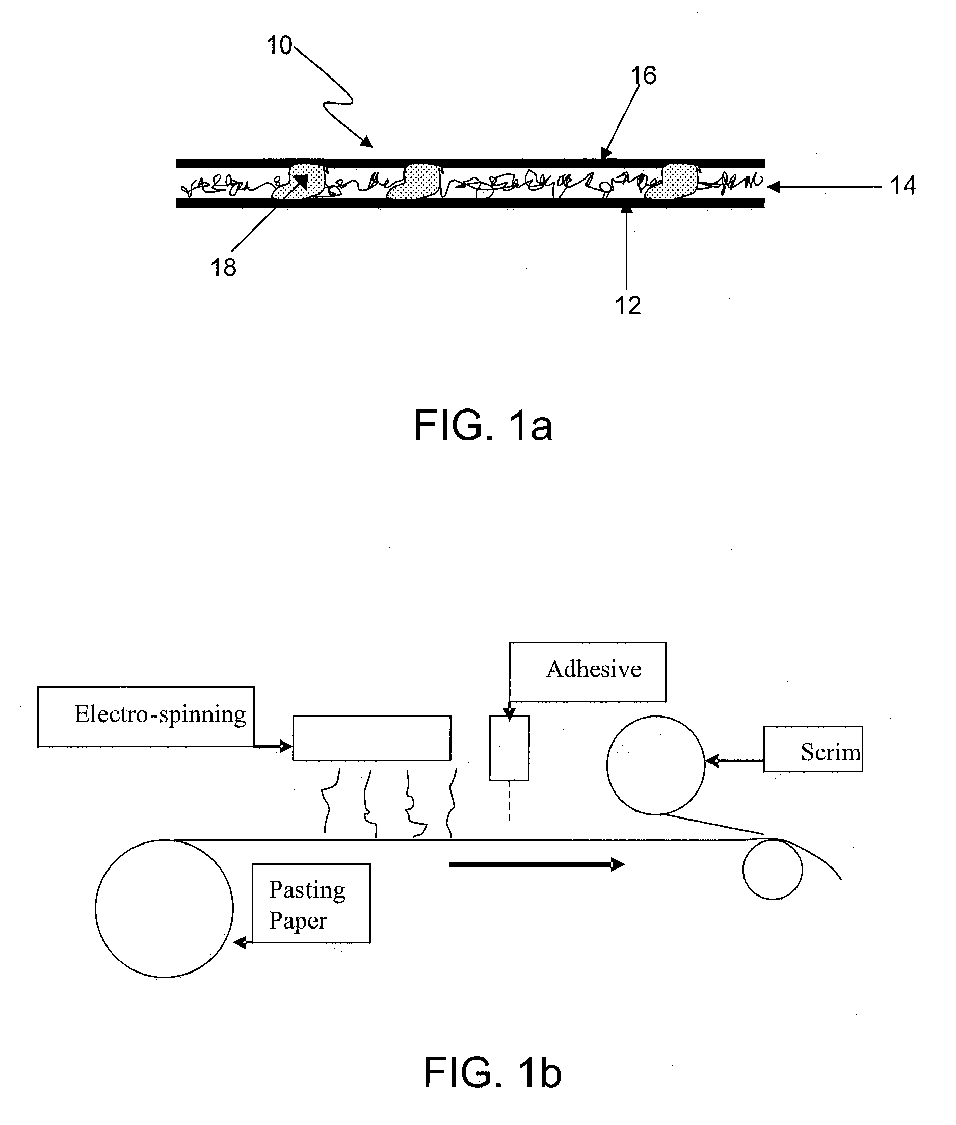
[0027]The invention will now be described with reference to the Figures, wherein similar numbers indicate similar features. The figures depict certain nonlimiting embodiments of the invention. FIGS. 1a, 1b and 5 are not to scale, and are not intended to serve as engineering drawings.

[0028]The invention provides a multilayer composite sheet suitable for use as a battery separator, shown schematically in FIG. 1a. In some embodiments, the sheet may be used as a combined battery pasting paper / separator, as will now be discussed. The sheet, shown generally at 10, includes a fibrous layer 12 upon which resides an electrically nonconductive polymeric nanofiber layer 14, upon which in turn resides a polymeric scrim layer 16. In the present case, the fibrous layer 12 is a pasting paper. Discrete particles of adhesive 18 adhere the nanofiber layer to both the paper layer and the scrim layer, thereby integrating the three layers to form the composite sheet. In this particular embodiment, the a...


PUM

PropertyMeasurementUnit
Pore sizeaaaaaaaaaa
Pore sizeaaaaaaaaaa
Thicknessaaaaaaaaaa

Abstract

A multilayer composite sheet for use in a lead-acid battery includes
    • a) a base layer including paper or a glass fiber mat;
    • b) a layer of polymeric nanofibers bonded with discrete adhesive particles to a first surface of the base layer; and
    • c) a scrim layer bonded with discrete adhesive particles to a surface of the layer of nanofibers opposite the base layer.
A plate assembly for a lead-acid battery includes one or more multilayer composite sheets located adjacent or partially enclosing a lead plate.

Description

CROSS REFERENCE TO RELATED APPLICATIONS[0001]This application claims priority benefit of U.S. Provisional Appln. No. 61 / 007,082, filed Dec. 11, 2007, the entirety of which is incorporated herein by reference.BACKGROUND OF THE INVENTION[0002]Lead-acid batteries contain lead plates that may be prepared by applying an aqueous paste of lead oxide (PbO) to a lead grid and then drying the grid. In some methods, for example continuous casting methods, the lead oxide is held in place by a pasting paper while the plate is dried. In other methods, such as strip casting methods, pasting paper is not needed.[0003]Once dry, the plates are “formed” by applying an electrical charge to the plates while they are immersed in a 6 molar sulfuric acid solution, resulting in the creation of positive and negative plates. Newer production methods involve addition of expander materials (powdered sulfates) to the paste to produce negative plates, thereby eliminating the need to form the plates. In either cas...

Claims


Application Information

Patent Timeline
IPC IPC(8): H01M2/16H01M50/417H01M50/423H01M50/437H01M50/451H01M50/457H01M50/491
CPCH01M2/1613H01M2/162H01M2/1626Y02E60/126H01M2/1686H01M4/14H01M10/06H01M2/1673Y10T442/197Y10T442/174Y10T442/155Y10T442/159Y10T442/184Y02E60/10H01M50/44H01M50/4295H01M50/46Y02P70/50H01M50/437H01M50/417H01M50/451H01M50/457H01M50/491H01M50/423H01M50/431H01M50/411H01M50/449B82Y30/00
Inventor JUSTICE, WILLIAM N.
Owner GLATFELTER CORP
Why Eureka
Try Eureka