

Semiconductor device and method for manufacturing the same
a semiconductor and semiconductor technology, applied in semiconductor devices, semiconductor/solid-state device details, electrical devices, etc., can solve the problems of short circuit between the contact plug and the semiconductor substrate, the accuracy of aligning the contact hole, and the difficulty of forming the contact plug
- Summary
- Abstract
- Description
- Claims
- Application Information
AI Technical Summary
Benefits of technology
Problems solved by technology
Method used
Image

Examples
first exemplary embodiment
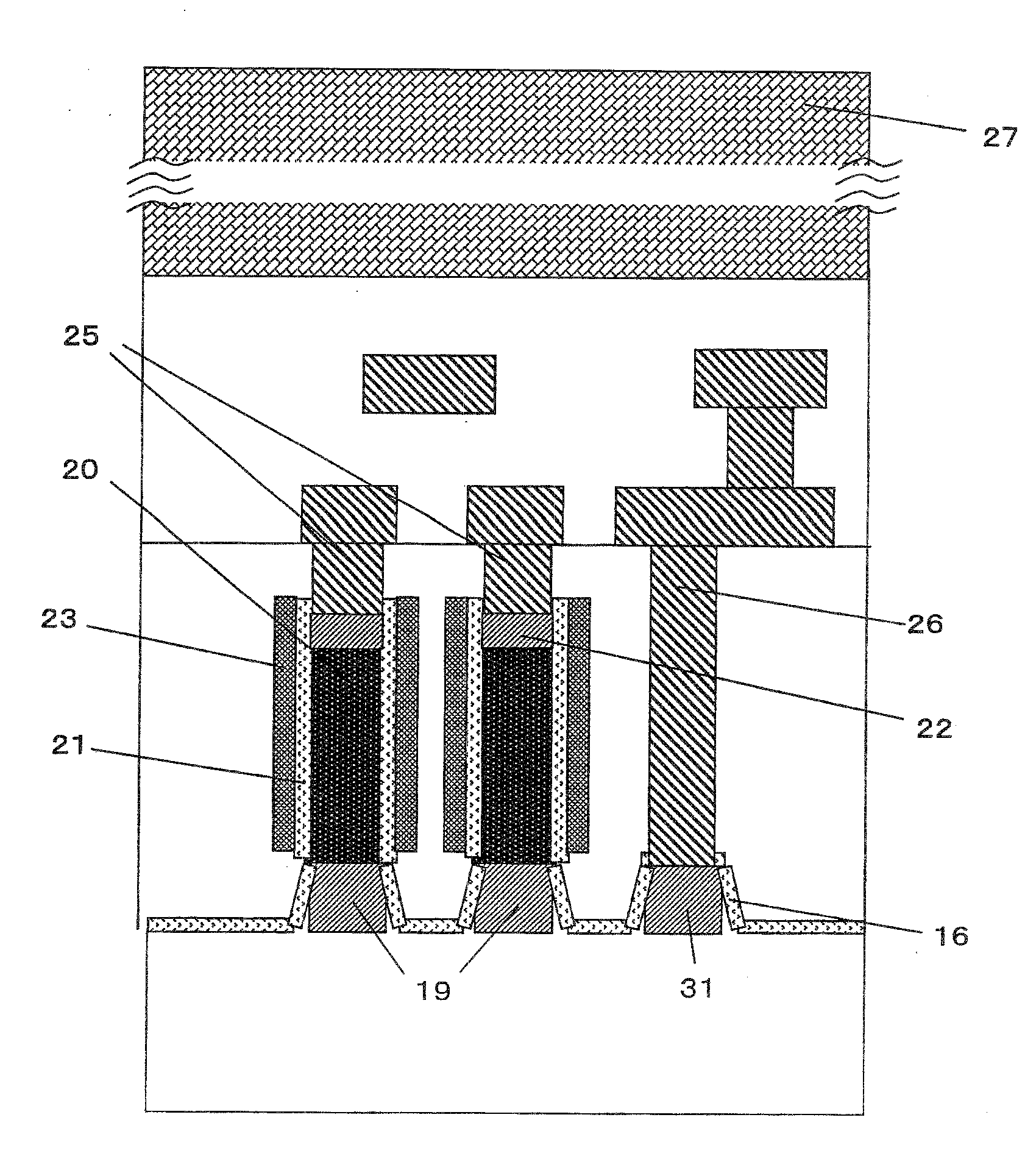
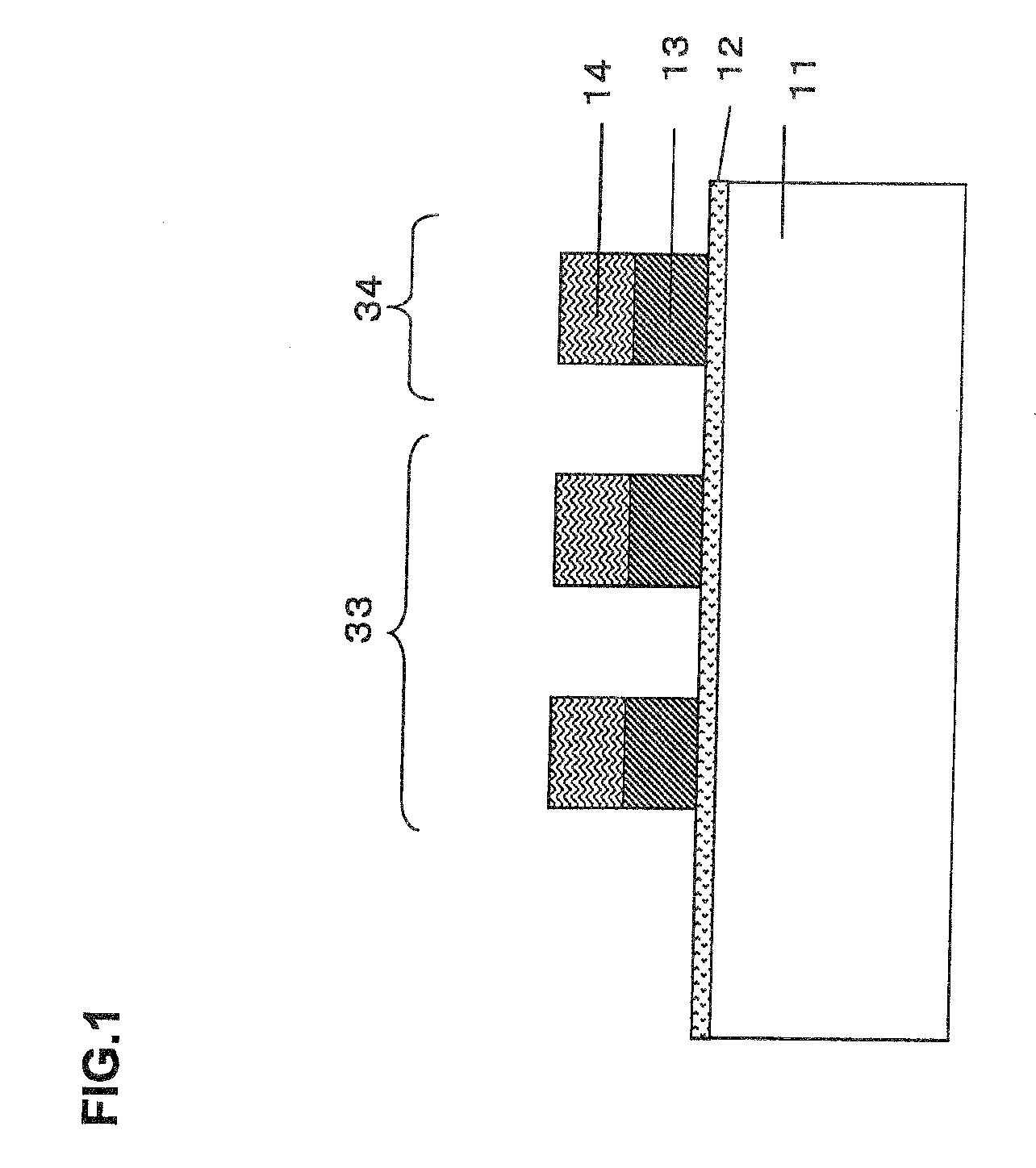
[0108]The first exemplary embodiment relates to a method for manufacturing a semiconductor device including a vertical MOSFET. The first exemplary embodiment includes:
(1) forming a first insulating layer across the entire surface of a semiconductor substrate;
(2) forming a first mask pattern on the first insulating layer;
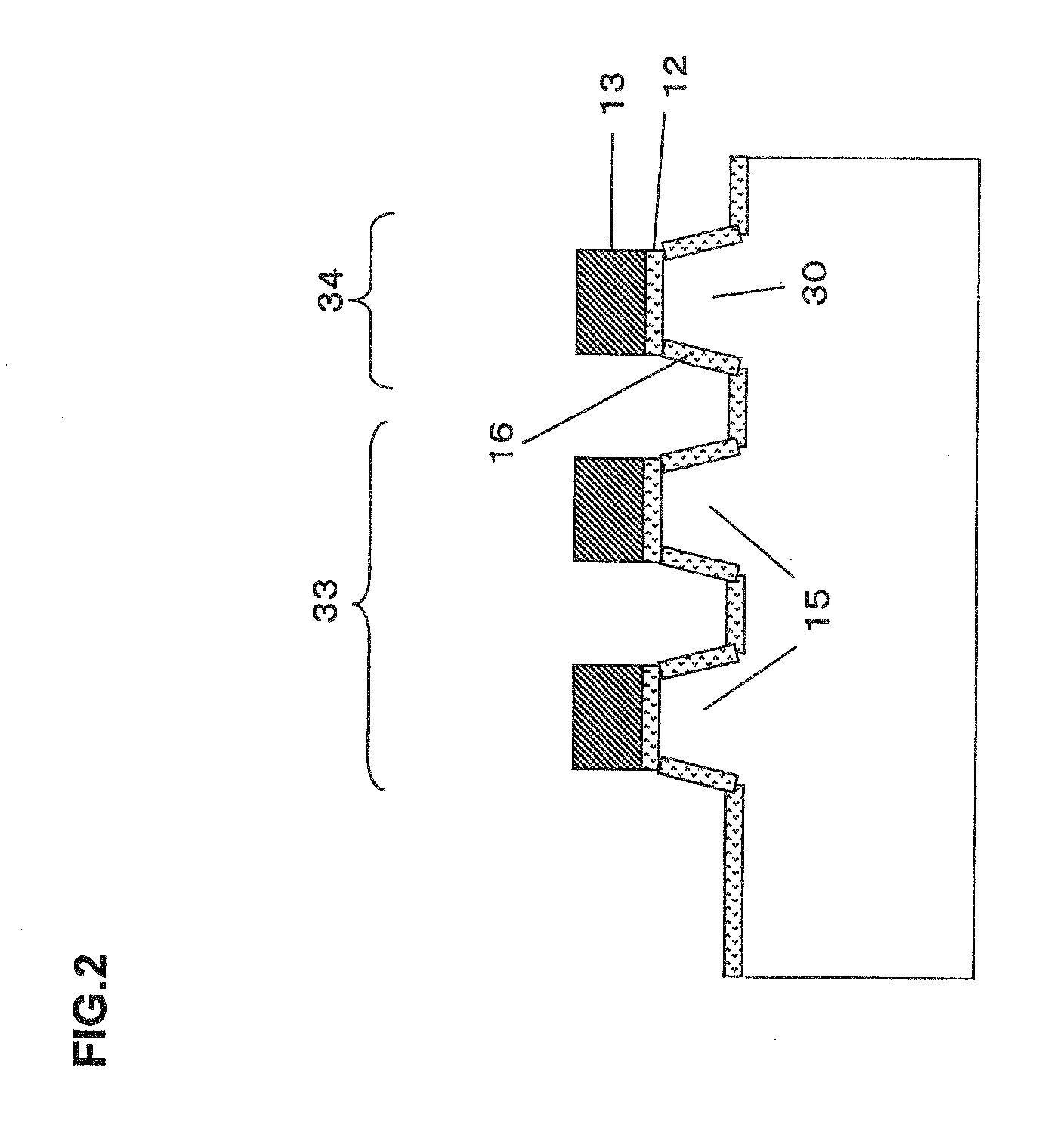
(3) etching the first insulating layer and the semiconductor substrate using the first mask pattern as a mask to form, below the first mask pattern, a protruding region a portion of which other than a portion below the first mask pattern is exposed;
(4) forming a second insulating layer in the exposed portion of the semiconductor substrate;
(5) removing the first mask pattern;
(6) forming a first interlayer insulating film over the entire surface of the semiconductor substrate;
(7-1) forming a first opening in a position corresponding to the protruding region within the first interlayer insulating film and removing the first insulating layer on the protruding region;
(7-2...
second exemplary embodiment
[0124]The second exemplary embodiment relates to a method for manufacturing a semiconductor device including a vertical MOSFET and an interconnect structure. The second exemplary embodiment includes:
(1) forming a first insulating layer across the entire surface of a semiconductor substrate;
(2) forming a first mask pattern on the first insulating layer;
(3) etching the first insulating layer and the semiconductor substrate using the first mask pattern as a mask to form, below the first mask pattern, a plurality of protruding regions composed of protruding regions A and B the portions of which other than portions below the first mask pattern are exposed;
(4) forming a second insulating layer in the exposed portions of the semiconductor substrate;
(5) removing the first mask pattern;
(6) forming a first interlayer insulating film over the entire surface of the semiconductor substrate;
(7-1) forming a first opening in a position corresponding to the protruding region A within the first inter...
third exemplary embodiment
[0136]The third exemplary embodiment relates to a method for manufacturing a semiconductor device including an interconnect structure. The third exemplary embodiment includes:
(1) forming a first insulating layer across the entire surface of a semiconductor substrate;
(2) forming a first mask pattern on the first insulating layer;
(3) etching the first insulating layer and the semiconductor substrate using the first mask pattern as a mask to form, below the first mask pattern, a protruding region a portion of which other than a portion below the first mask pattern is exposed;
(4) forming a second insulating layer in the exposed portion of the semiconductor substrate;
(5) removing the first mask pattern;
(6) forming a first interlayer insulating film over the entire surface of the semiconductor substrate,
(7-1) forming a first opening in a position corresponding to the protruding region within the first interlayer insulating film and removing the first insulating layer on the protruding reg...
PUM
 Abstract
Description
Claims
Application Information