Single layer dual band antenna with circular polarization and single feed point

a single-layer, circular polarization technology, applied in the direction of resonant antennas, substantially flat resonant elements, antenna earthings, etc., can solve the problems of low gain, narrow bandwidth, complex configuration of antennas, etc., and achieve high gain through coupling, simple structure, and wide bandwidth

Inactive Publication Date: 2009-06-18
E M W ANTENNA CO LTD
View PDF3 Cites 54 Cited by
  • Summary
  • Abstract
  • Description
  • Claims
  • Application Information

AI Technical Summary

Benefits of technology

[0020]According to the present invention, a thin dual-band circular polarization antenna having a simple structure can be obtained by forming radiators in a single layer and using a single feeding structure. The dual-band circular polarizatio

Problems solved by technology

This antenna has separate feeding elements for the respective radiators, and thus its configuration is complicated and the manufacturing cost is high.
Furthermore, this antenna has a narrow bandwidth and a low gain.
However, it is difficult to accurately control resonant frequencies of the radiators be

Method used


Image

  • Single layer dual band antenna with circular polarization and single feed point
  • Single layer dual band antenna with circular polarization and single feed point
  • Single layer dual band antenna with circular polarization and single feed point

Examples


Embodiment Construction

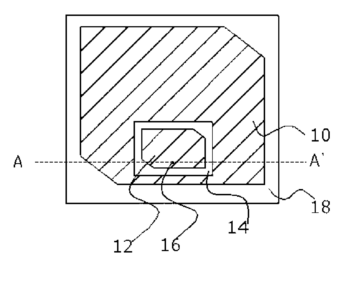
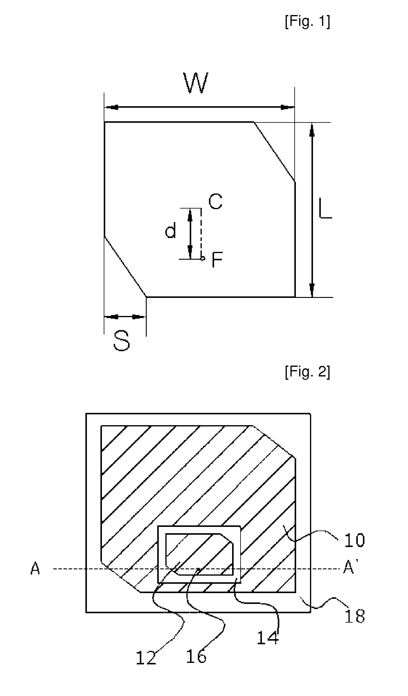
[0033]Before providing detailed description of specific embodiments of the present invention, a corner truncated rectangular patch antenna used as a radiator of a dual-mode circular polarization antenna according to an embodiment of the present invention will now be explained. FIG. 1 illustrates the corner truncated rectangular patch antenna.

[0034]Referring to FIG. 1, a rectangular patch has a length of L and a width of W and is fed at a feed point F. The resonant frequency of the rectangular patch antenna is roughly determined by the length L of the rectangular patch. The length L of the rectangular patch is set to approximately λ / 2 when the resonant wavelength of the antenna is λ. The width W of the rectangular patch is proportional to the bandwidth of the antenna. In the present embodiment, the length L and the width W of the rectangular patch may be equal to each other. Two opposite corners of the rectangular patch are truncated in the form of a right-angled (and equilateral) tr...


PUM


Abstract

A single-layer dual-band antenna with circular polarization is disclosed. The antenna includes a first radiator formed on the top surface of a substrate and electrically coupled to a feeding element, and a second radiator formed on the top surface of the substrate, spaced apart from the first radiator by a predetermined distance and electromagnetically coupled with the first radiator. The antenna is thin because it has a single-layer structure. Furthermore, there is no deterioration in the radiation characteristic due to interference between the radiators. Moreover, impedances of the radiators can be independently matched at their frequency bands by adjusting the position of a feed point and the relative position of the radiators.

Description

TECHNICAL FIELD[0001]The present invention relates to a dual-band circular polarization antenna, and more particularly, to a dual-band circular polarization antenna with a small size and easily controllable resonant frequency, which has two radiators formed on the same plane in such a manner as to be spaced apart from each other.BACKGROUND ART[0002]Recently, a radio frequency identification (RFID) system has been actively studied. FIG. 10 is a block diagram of a conventional RFID system. The conventional RFID system includes a transponder 100 that is also referred to as an RF tag and a reader / writer 200 having an antenna 210 and a transceiver 220. The transponder 100 is attached to an object that is to be identified, such as products, vehicles, the human body, animals and so on, and stores identification information and state information of the object. The transponder 100 can perform wireless communication with the reader 200 through an antenna (not shown) included therein. The read...

Claims


Application Information

Patent Timeline
IPC IPC(8): H01Q5/01H01Q5/10
CPCH01Q9/0407H01Q5/378H01Q9/0428H01Q1/2216H01Q1/38
Inventor RYOU, BYUNG-HOONSUNG, WON-MOKIM, JEONG-PYO
Owner E M W ANTENNA CO LTD
Why Eureka
Try Eureka