Capacitive coupling-type transmitting and receiving circuits for information signal

a technology of information signal and transmitting circuit, which is applied in static indicating devices, instruments, cathode-ray tube indicators, etc., can solve the problems of high power consumption of circuits, increased equipment area, and difficulty in transmitting through these methods using thin film transistors on display panels. , to achieve the effect of reducing input margin, reducing power consumption, and suppressing attenuation of signals

Inactive Publication Date: 2009-06-18
PANASONIC LIQUID CRYSTAL DISPLAY CO LTD +1
View PDF6 Cites 10 Cited by
  • Summary
  • Abstract
  • Description
  • Claims
  • Application Information

AI Technical Summary

Benefits of technology

[0017]With the various aspects of the present invention, the following advantages were realized; (1) because the impedance converter circuit is provided near the receiving capacitor electrode on a display panel board which is the receiving board, it is possible to suppress attenuation of signals in the non-contact transmission path via the capacitor and a change in the receiving side voltage due to a slight change in capacitance; (2) because the reference signal (clock signal) is separated from the display data signal, the modulation and demodulation of the signal becomes unnecessary and non-contact transmission is enabled which does not depend on the magnitude of the transmission rate or on the presence or absence of data; (3) reduction of an input margin on the side of the display panel due to a change in a direct current component (offset component) cont...

Problems solved by technology

Because of this, a high processing capability (response speed) is required for the circuit element on the side of the display panel, and it is difficult to transmit through these methods using a thin film transistor (TFT) on the display panel.
In addition, the power consumption of the circuit is high.
Moreover, in the electromagnetic induction method, a coil and a capacitor for resonance must be formed for each...

Method used


Image

  • Capacitive coupling-type transmitting and receiving circuits for information signal
  • Capacitive coupling-type transmitting and receiving circuits for information signal
  • Capacitive coupling-type transmitting and receiving circuits for information signal

Examples


first preferred embodiment

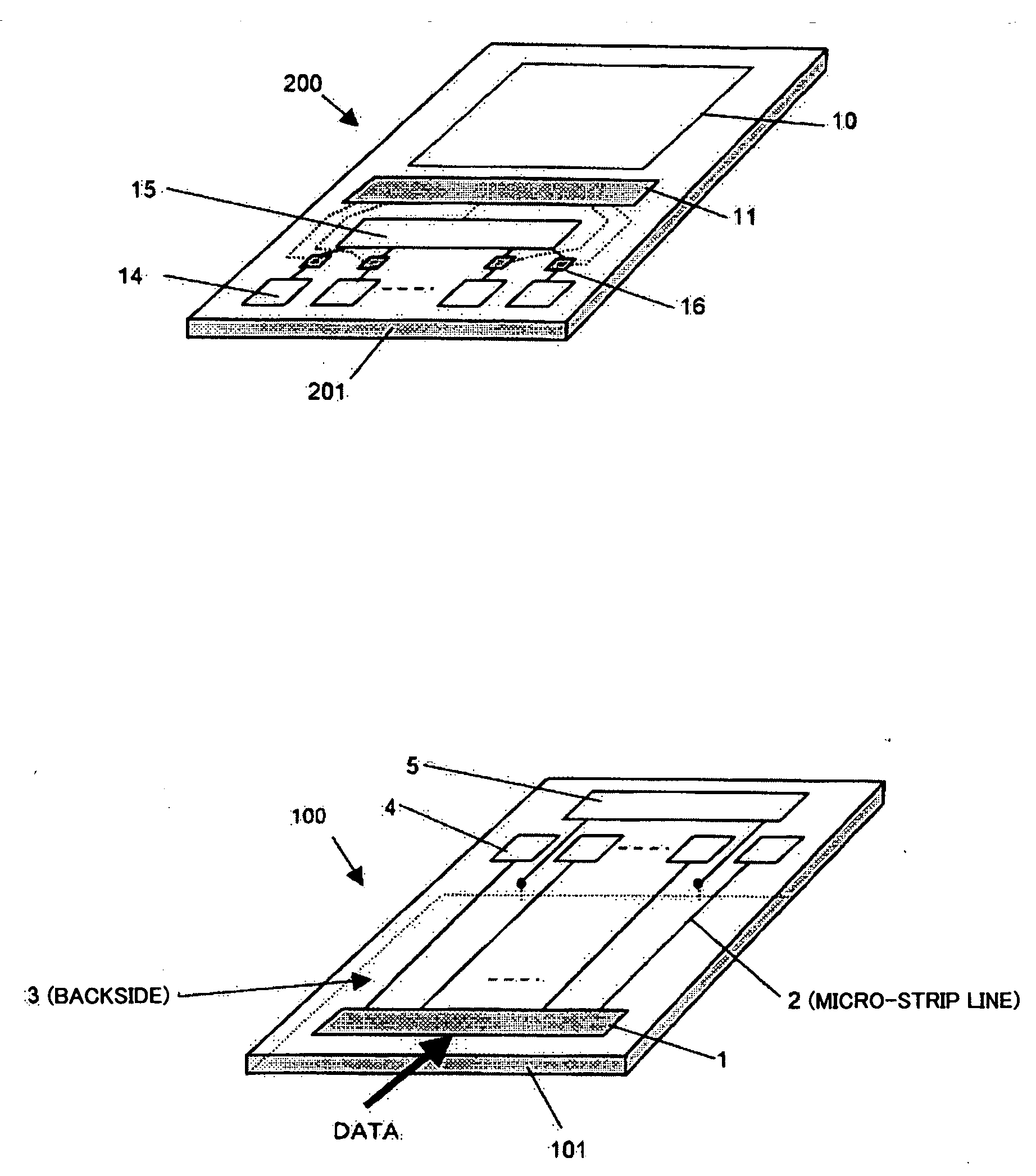
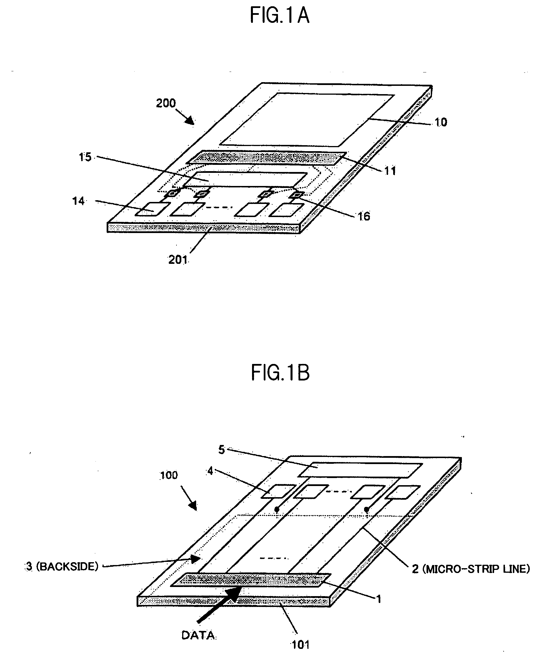
[0032]FIGS. 1A and 1B are schematic structural diagrams of a display apparatus for explaining a first preferred embodiment of the present invention. In the display apparatus, the capacitive coupling-type transmitting and receiving circuit for information signal of the present invention is equipped. FIG. 1A shows a display panel board 200 and FIG. 1B shows a transmitting board 100. In the display panel board 200, a display section 10 is formed or equipped over an insulating board 201 which is preferably made of glass. The display section 10 refers to a liquid crystal display apparatus or the like. In addition, a reception signal processing circuit 11, a plurality of receiving capacitor electrodes 14 and 15, and an impedance converter circuit 16 connected to the receiving capacitor electrode 14 are formed over the insulating board 201. The receiving capacitor electrode 15 is provided for maintaining a common potential for the other receiving capacitor electrodes.

[0033]On the other han...

second preferred embodiment

[0053]FIGS. 9A and 9B are schematic structural diagrams of a display apparatus for explaining a second preferred embodiment of the present invention. Similar to FIGS. 1A and 1B, structures of a transmitting board which transmits a display signal via a non-contact transmission path and of a display panel which receives the display signal via the non-contact transmission path are shown. A same reference numeral is assigned to a function portion which is identical to that of FIGS. 1A and 1B. In FIGS. 9A and 9B, a case is considered in which one transmission signal is transmitted by two capacitive coupling electrodes assigned for each signal (balanced transmission).

[0054]The operation at the transmitting board 100 is approximately similar to that of the first preferred embodiment. In the case of the balanced transmission, the transmission line 2 comprises a pair (two lines) of transmission lines including a signal line and an inverted signal line, and the structure is completely symmetr...

third preferred embodiment

[0056]FIGS. 11A and 11B are diagrams which show another example structure of and an operation waveform of the pulse logic-to-level logic converter circuit 16 provided on the display panel board, for explaining a third preferred embodiment of the present invention. FIG. 11A shows another example structure of the pulse logic-to-level logic converter circuit on the side of the display panel board 200. As described above, the converter circuit 16 of FIG. 8A shown in the first preferred embodiment has a limitation on the timing for the data input. The circuit of FIGS. 11A and 11B, on the other hand, can detect a rise of the data input independently of logic states of the clock signal CL.

[0057]The converter circuit 16 primarily comprises three D-flip-flops 331, 332, and 34. An operation of the circuit will now be described along with the voltage waveforms shown in FIG. 11B. The data signal DATA and the clock signal CL which are induced on the side of the display panel board 200 are conver...


PUM


Abstract

A capacitive coupling-type transmitting and receiving circuit for information signal is provided in which attenuation of a signal on a non-contact transmission path via a capacitor and a change of voltage on the receiving side due to a slight change in capacitance are suppressed, modulation and demodulation processes of signals are unnecessary, and non-contact transmission which does not depend on the transmission rate is enabled. The capacitor is formed with a transmitting electrode on a transmission board and a receiving electrode on a display panel board, and an insulating member is interposed between the electrodes. The transmitting board comprises a transmission signal processing circuit which converts display data from an external signal source into a voltage signal. The display panel board comprises an impedance converter circuit and a reception signal processing circuit.

Description

CLAIM OF PRIORITY[0001]The present application claims priority from Japanese application JP 2007-321595 filed on Dec. 13, 2007, the content of which is hereby incorporated by reference into this application.BACKGROUND OF THE INVENTION[0002]1. Field of the Invention[0003]The present invention relates to a captive coupling-type transmitting and receiving circuit for information signal, for non-contact transmission of display information from a signal source to a display panel, and, in particular, to such a circuit preferable for a portable information terminal for which a low power consumption is desired.[0004]2. Description of the Related Art[0005]If display information to a display panel such as a liquid crystal panel and an organic electroluminescence panel is electrically transmitted from a signal source in a non-contacting system, the line materials to be provided on the display panel can be omitted, and, consequently, the cost of the panel equipment can be reduced and fabricatio...

Claims


Application Information

Patent Timeline
IPC IPC(8): G09G3/30
CPCG09G5/006H04B5/0012G09G5/008
Inventor FURUTA, FUTOSHIKAGEYAMA, HIROSHITAKEI, KEN
Owner PANASONIC LIQUID CRYSTAL DISPLAY CO LTD
Why Eureka
Try Eureka