Optical transmission module and manufacturing method of the same

Inactive Publication Date: 2009-06-18
NEC CORP
View PDF10 Cites 14 Cited by
  • Summary
  • Abstract
  • Description
  • Claims
  • Application Information

AI Technical Summary

Benefits of technology

[0022]According to the present invention, either the first or the second optical device is fixed on the carrier, and the other is closely contacted with the second surface (a surface vertical to the optical axis) of the element support member and fixed thereon. According to this structure, after the optical axis of the other optical device is aligned with the optical axis of the remaining optical device in an X-Y plain surface, the other optical device can b

Problems solved by technology

However, it needs a very long Er doped optical fiber and a very large LD module for excitation, so that it is disadvantageous in that it becomes expen

Method used


Image

  • Optical transmission module and manufacturing method of the same
  • Optical transmission module and manufacturing method of the same
  • Optical transmission module and manufacturing method of the same

Examples


first exemplary embodiment

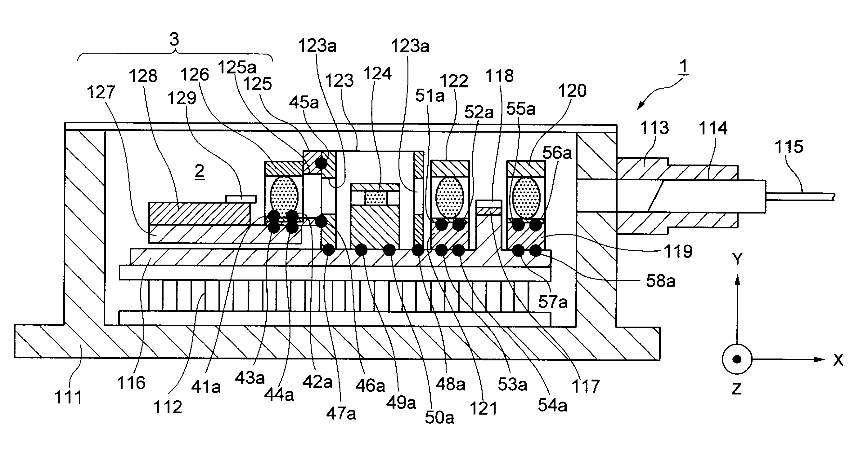
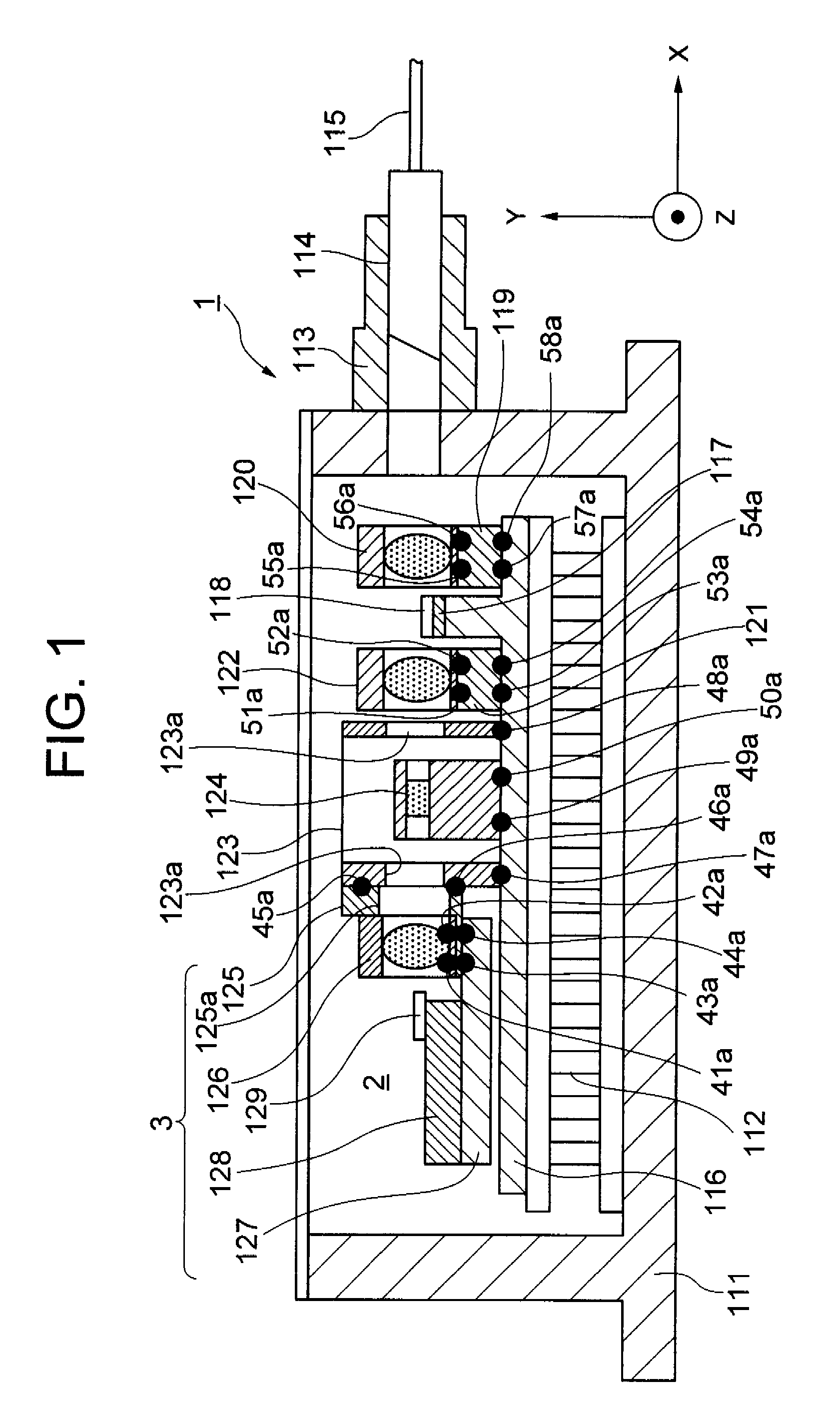
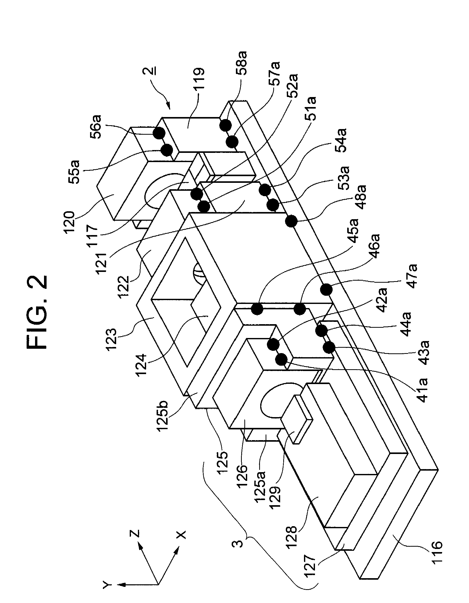
[0024]FIG. 1 is a cross-sectional view showing an optical transmission module according to a first exemplary embodiment of the invention. FIG. 2 is a perspective view showing an optical transmission unit in the first exemplary embodiment.

[0025]As shown in FIGS. 1 and 2, an optical transmission module 1 is composed of a package 111, a peltier device 112 which is placed in the package 111 and controls temperature of an optical transmission unit 2, the optical transmission unit 2 placed on the peltier device 112, a fiber support 113 which is put on an opening of the package 111, a ferrule 114 supported by the fiber support 113, and an optical fiber 115 held by the ferrule 114.

[0026]The optical transmission unit 2 is composed of a carrier 116 which becomes a base, a first optical device 118 which is attached on the carrier 116 through a first sub carrier 117, a first and a second lens 120, 122 fixed on a carrier through a first and a second lens holder 119, 121, an element support membe...

second exemplary embodiment

[0032]FIG. 3 is a perspective view showing an optical transmission unit according to second exemplary Embodiment of the invention. The optical transmission unit 2 is mounted within a package to which a peltier device, a ferrule and the like are attached, as well as the case in the first exemplary embodiment shown in FIG. 1.

[0033]In FIG. 3, the same components as in FIG. 2 have identical reference numerals, and the same explanation will be omitted accordingly. In the exemplary embodiment, the third lens holder 125 is in a simple U-shape. The small carrier 127 is formed such that a longitudinal section of the small carrier 127, which is parallel to the optical axis, is an L-shaped. The small carrier 127 closely contacts with the element support member 123, and welded to the element support member 123 at welding point 59a and 60a. That is, in the exemplary embodiment, the small carrier 127 includes an element mounting part 127a which is parallel to the carrier 116 and an upright part 1...

third exemplary embodiment

[0037]FIG. 5 is a perspective view of an optical transmission unit according to a third exemplary embodiment of the invention, and FIGS. 6(a) and 6(b) are cross-sectional views respectively taken along lines A-A and B-B in FIG. 5.

[0038]The optical transmission unit 2 of the third exemplary embodiment is mounted within a package to which a peltier device, a ferrule and the like are attached as well as the case in the first exemplary embodiment. In FIG. 5, the same components as in FIG. 2 have identical reference numerals, and the same explanation will be omitted accordingly.

[0039]In the exemplary embodiment, the element support member 123 includes a small carrier holding part 123a having a cross-section, which is vertical to the optical axis, of U-shaped, for housing the small carrier 127, and an upstanding part 123b having a surface vertical to the optical axis. The element support member 123 closely contacts with an upper surface of the carrier 116 at a bottom surface of the member...


PUM

PropertyMeasurementUnit
Pressureaaaaaaaaaa
Shapeaaaaaaaaaa

Abstract

[Problems] To accommodate a plurality of optical semiconductor elements in one package with their optical axes aligned highly precisely.
[Means for Solving the Problems] An optical transmission module includes an optical transmission unit, a carrier to become a base, a semiconductor optical amplification element mounted on the carrier through a first sub-carrier, first and second lenses fixed on the carrier through first and second lens holders, an element supporting member and an optical isolator fixed on the carrier, a third lens holder supported by the element supporting member, a third lens and a small carrier individually fixed in the third lens holder, and a semiconductor laser element mounted on the small carrier through a second sub-carrier.

Description

TECHNICAL FIELD[0001]The present invention relates to an optical transmission module used for an optical communication system and a manufacturing method thereof, in particular, to an optical transmission module including a plurality of optical devices such as a semiconductor laser, a semiconductor optical amplifier, and the like in a same package and a manufacturing method thereof.BACKGROUND ART[0002]Along with increase in demand for optical communication in recent years, an optical communication system in smaller size with lower cost is strongly required to be provided. To construct an optical communication system with high reliability and low cost, it is important that the system can transmit data for a long distance without relay. As a way to perform it, an optical fiber amplifier and an optical semiconductor amplifier have been known. In the former case, an Er doped optical fiber is excited by an LD module for excitation. However, it needs a very long Er doped optical fiber and ...

Claims


Application Information

Patent Timeline
IPC IPC(8): H01S5/50G02B7/02B23K28/00
CPCG02B6/4201G02B6/4204H01S5/005H01S5/0064H04B10/40H01S5/02272H01S5/02284H01S5/02415H01S5/50H01S5/02248G02B6/4271G02B6/4244G02B6/4245G02B6/4257G02B6/424H01S5/0237H01S5/02325H01S5/02251
Inventor KANEMOTO, MITSUNORIKANEKO, TAROU
Owner NEC CORP
Why Eureka
Try Eureka