System and method for controlling the cooling of variable heat loads in heat generating devices

a variable heat load and heat generating device technology, applied in the field of cooling of electrical, electronic and optical components, can solve the problems of damage to electrical or electronic devices, high temperature and/or large flow rate, and the inability to use sensible heating of fluid to remove heat from electrical and electronic components

Inactive Publication Date: 2009-06-25
MARSALA JOSEPH
View PDF0 Cites 17 Cited by
  • Summary
  • Abstract
  • Description
  • Claims
  • Application Information

AI Technical Summary

Benefits of technology

[0010]This need is met by the system and method of the present invention of providing control of the operation of two phase cooling loops to account for rapid changes in thermal load.

Problems solved by technology

This method of using the sensible heating of a fluid to remove heat from electrical and electronic components is limited by the thermal capacity of the single phase flowing fluid.
This creates high temperatures and / or large flow rates to cool high power microelectronic devices.
High temperatures may damage the electrical or electronic devices, while large flow rates require pumps with large motors which consume parasitic electrical power and limit the application of the cooling system.
Large flow rates may also cause erosion of the metal in the cold plate due to high fluid velocities.
This method of removing heat is limited by the ability of the wick structure to transport fluid to the evaporator.
At high thermal fluxes, a condition known as “dry out” occurs where the wick structure cannot transport enough fluid to the evaporator and the temperature of the device will increase, perhaps causing damage to the device.
Finally, heat pipes cannot transport heat over long distances to remote dissipaters due once again to capillary pumping limitations.
Yet another method which is employed when direct air-cooling is not practical uses the well-known vapor compression refrigeration cycle.
However, this method suffers from some major disadvantages which limit its practical application in cooling electrical and electronic devices.
First, there is the power consumption of the compressor.
In high thermal load applications the electric power required by the compressor can be significant and exceed the available power for the application.
Another problem concerns operation of the evaporator (cold plate) below ambient temperature.
In this case, poorly insulated surfaces may be below the dew point of the ambient air, causing condensation of liquid water and creating the opportunity for short circuits and hazards to people.
This can cause damage and shorten the life of the compressor.
This is yet another disadvantage of vapor compression cooling of components.
However, in cooling electrical, electronic and optical devices, often the heat load to be removed changes rapidly almost to the point of being instantaneous.
The simplest method is also the most inefficient, that is to operate the fan in the air cooled heat sink or the pump in a single phase cold plate loop to the maximum required flowrate at all times. This is wasteful of energy and can cause premature failure of the fan or pump since they must run at full capacity all the time.
This adds cost and complexity to the cooling system and sensors are required to tell when more cooling is required.
The situation with vapor compression cycle cooling is even more difficult because the compressor can be damaged by unevaporated liquid due to sudden changes in thermal load.
These variable speed compressors, suction accumulators and associated controls are expensive and complex.

Method used


Image

  • System and method for controlling the cooling of variable heat loads in heat generating devices
  • System and method for controlling the cooling of variable heat loads in heat generating devices
  • System and method for controlling the cooling of variable heat loads in heat generating devices

Examples


Embodiment Construction

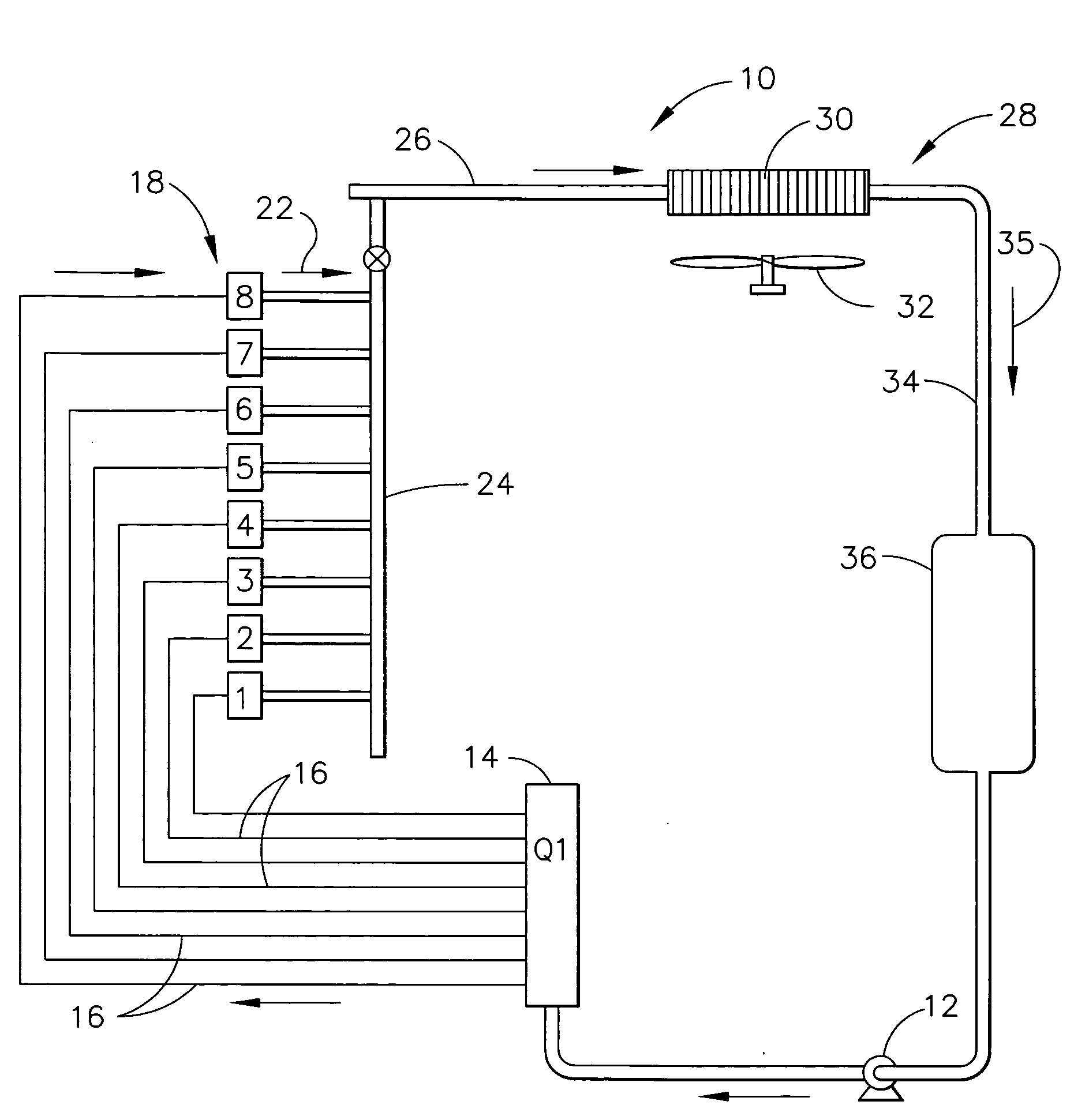
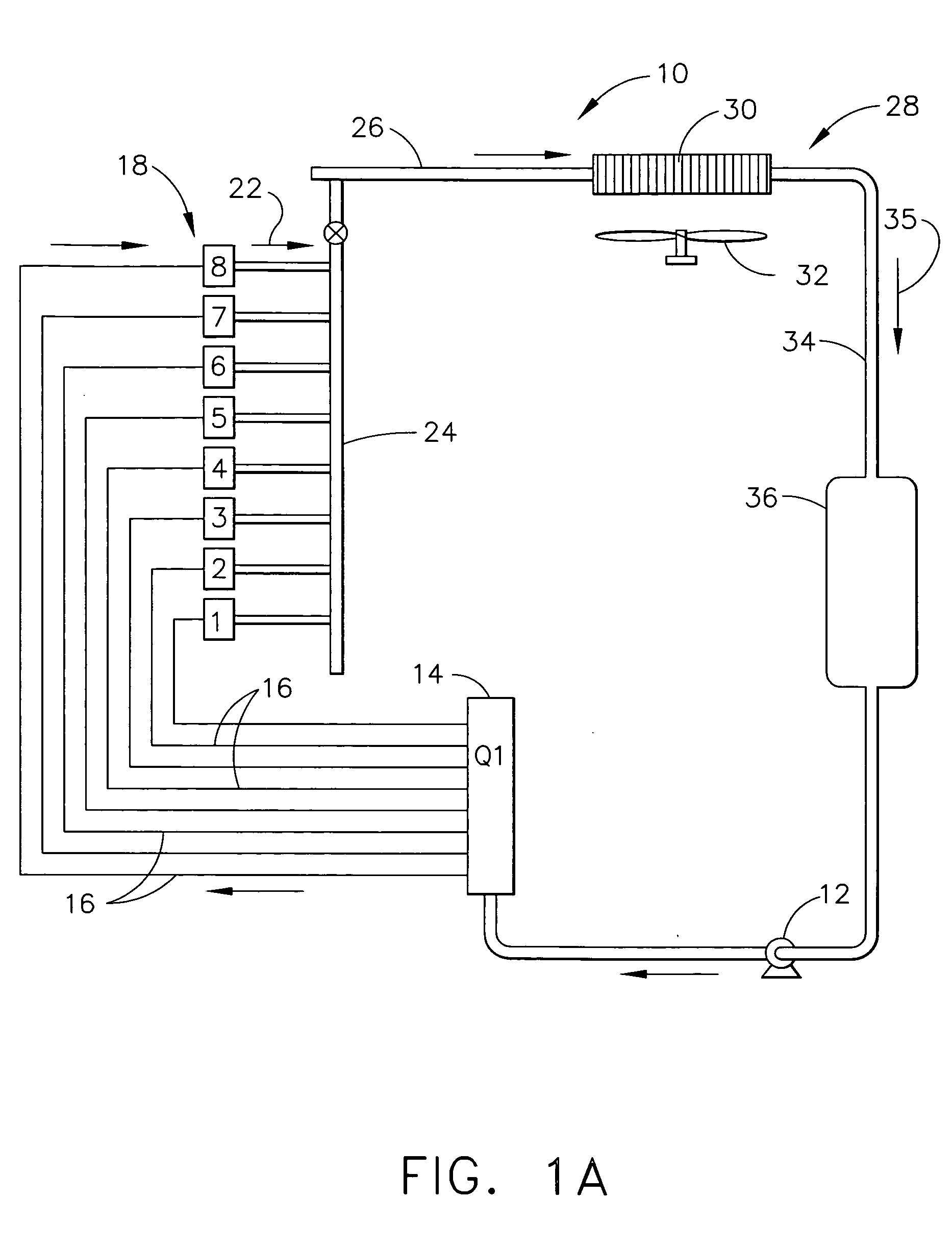
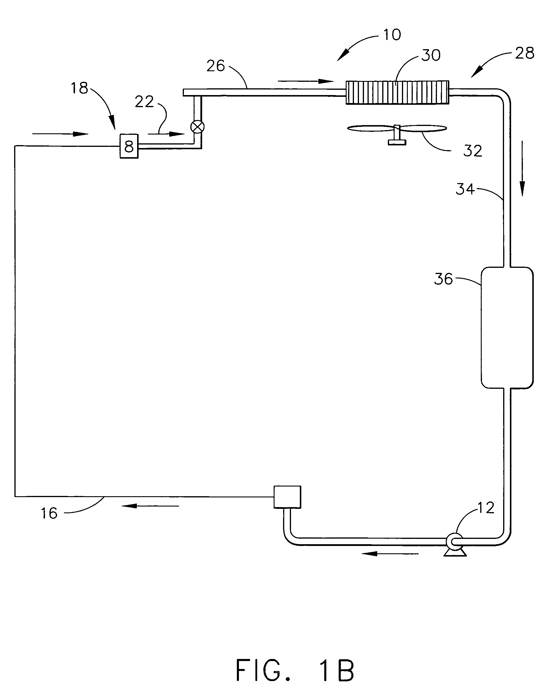
[0018]Referring now to FIGS. 1A and 1B, there is illustrated a cooling system 10 which circulates a refrigerant as the working fluid. The refrigerant may be any suitable vaporizable refrigerant, such as R-134a. The cooling cycle can begin at liquid pump 12, shown as a Hermetic Liquid Pump. Pump 12 pumps the liquid phase refrigerant to a liquid manifold 14, where it is distributed to one or a plurality of branches or lines 16. From the manifold 14, each branch or line 16 feeds liquid refrigerant to a cold plate 18. The condensing temperature of the refrigerant is preferably controlled so as to be above the ambient dew point where the cold plate evaporator device is located.

[0019]As illustrated in FIG. 2, each cold plate 18 is in thermal contact with an electrical or electronic component or components 20 to be cooled, causing the liquid refrigerant to evaporate at system pressure. None, some, or all of the liquid refrigerant may evaporate at cold plate 18, depending on how much heat i...


PUM


Abstract

The present invention offers an improvement over prior art cooling systems by accounting for rapid changes in thermal load. The circulation rate of refrigerant in a cooling cycle is set so that the two phase mixture exiting the cold plate evaporator device stays within a saturation dome of all mixtures between a saturated liquid and a saturated vapor. Furthermore, the two phase mixture exiting the cold plate evaporator device is allowed to move within the saturation dome so that the exit quality of the two phase mixture leaving the cold plate evaporator device changes with the heat load being removed. In this way, rapid changes in heat load are removed from the component or components in contact with the cold plate evaporator device without having to change the circulation rate of refrigerant in the cycle. Only the exit quality of the vapor leaving the cold plate/evaporator changes.

Description

TECHNICAL FIELD [0001]The present invention relates to cooling of electrical, electronic and optical components, and more particularly, to using a pumped liquid two phase cooling system to cool heat generating devices, including microprocessor semiconductors and power semiconductors, during rapid thermal load changes.BACKGROUND OF THE INVENTION [0002]Electrical, electronic and optical components (e.g. microprocessors, IGBT's, power semiconductors etc.) are most often cooled by air-cooled heat sinks with extended surfaces, directly attached to the surface to be cooled. A fan or blower moves air across the heat sink fins, removing the heat generated by the component. With increasing power densities, miniaturization of components, and shrinking of packaging, it is sometimes not possible to adequately cool electrical and electronic components with heat sinks and forced air flows. When this occurs, other methods must be employed to remove heat from the components.[0003]One method for rem...

Claims


Application Information

Patent Timeline
Patent Type & Authority Applications(United States)
IPC IPC(8): F25D15/00F25B1/00F25D3/10F25B39/02
CPCF25B23/006H01L23/427H01L23/473F28D15/0266H01L2924/0002H01L2924/00
Inventor MARSALA, JOSEPH
Owner MARSALA JOSEPH
Why Eureka
Try Eureka