Internal combustion engine control apparatus

a control apparatus and combustion engine technology, applied in the direction of electrical control, process and machine control, instruments, etc., can solve the problems of complex calculation formula for determining parameters, parameter cannot be easily calculated by a present-day vehicle-mounted computer, and calculations are extremely difficul

Active Publication Date: 2009-06-25
TOYOTA JIDOSHA KK
View PDF1 Cites 26 Cited by
  • Summary
  • Abstract
  • Description
  • Claims
  • Application Information

AI Technical Summary

Benefits of technology

[0050]According to the twenty-second aspect of the present invention, the relationship information can be used to exercise torque (combustion) control in accordance with the desired required torque. This aspect of the present invention also makes it possible, for instance, to control the valve overlap amount and ignition timing without making the intake air amount excessive or insufficient and without retarding the ignition timing.

Problems solved by technology

However, the calculation formula for determining the parameter is complicated.
Therefore, the parameter cannot easily be calculated by a present-day vehicle-mounted computer (ECU).
In reality, however, such calculations are extremely difficult because the computation load is heavy.
However, the above conventional technology cannot estimate the in-cylinder pressure P(θ) and needs further improvement.

Method used


Image

  • Internal combustion engine control apparatus
  • Internal combustion engine control apparatus
  • Internal combustion engine control apparatus

Examples


first embodiment

[0072][System Configuration Description]

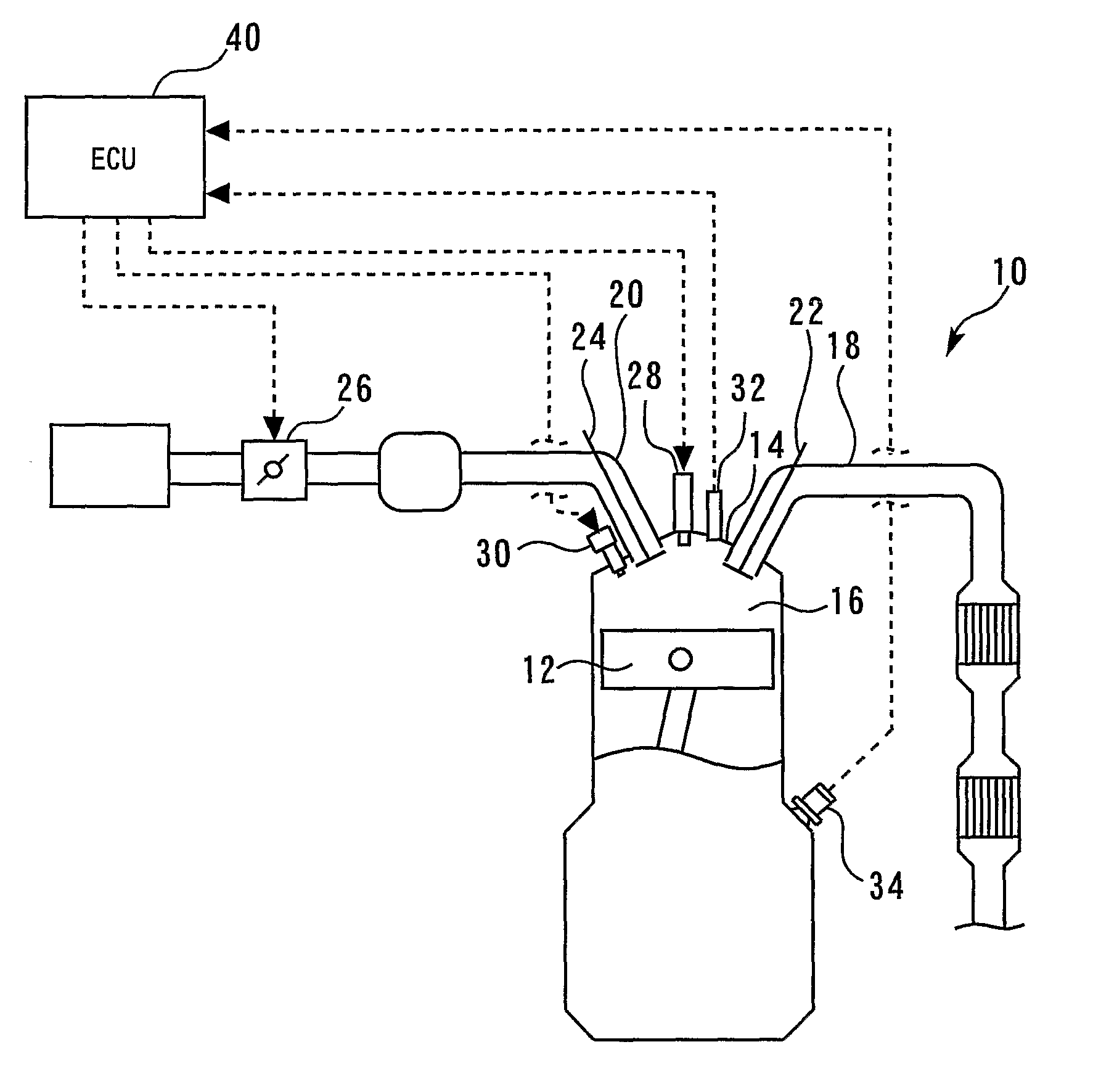
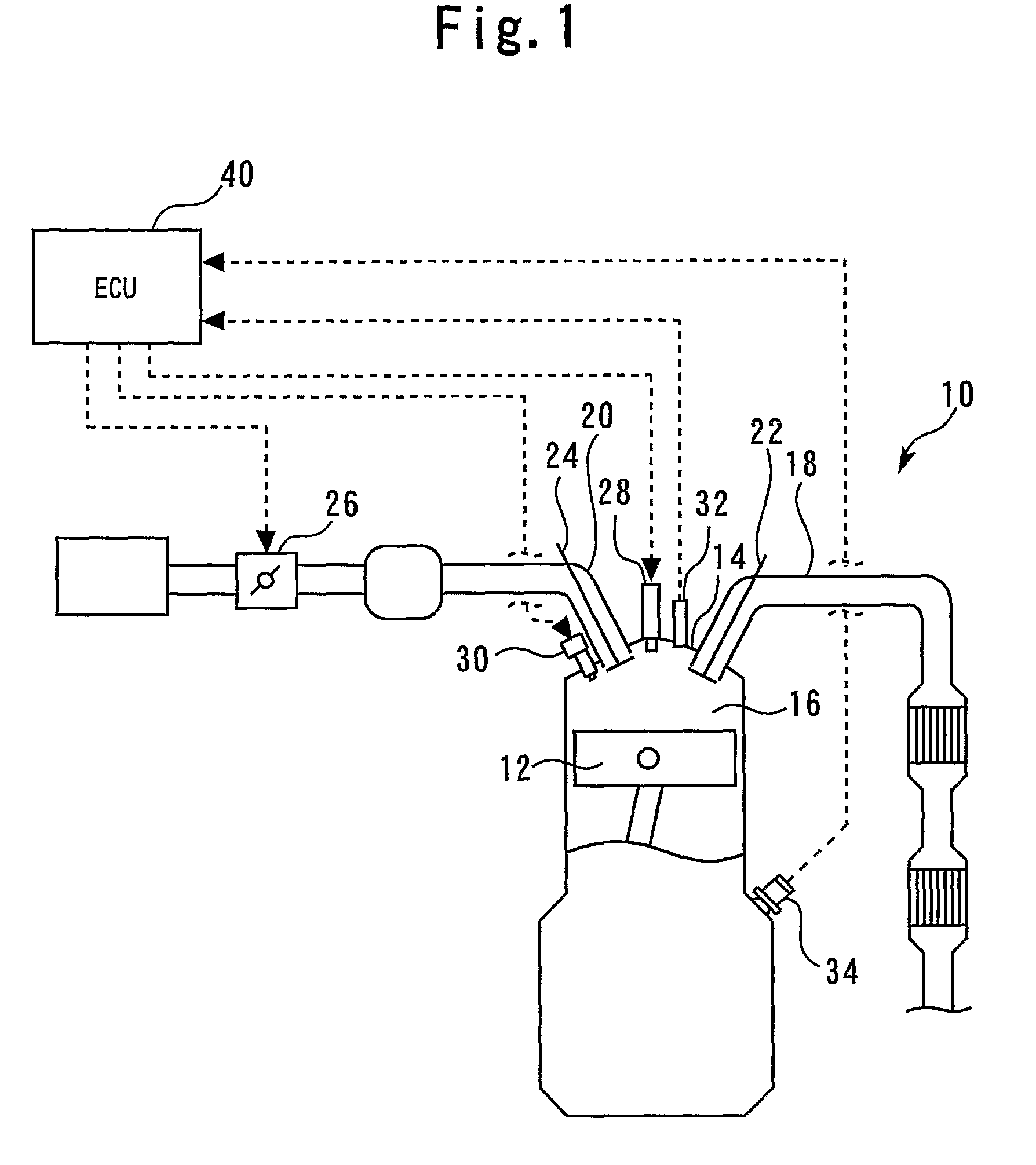
[0073]FIG. 1 illustrates the configuration of a first embodiment of the present invention. As shown in FIG. 1, the system according to the present embodiment includes an internal combustion engine 10. A cylinder in the internal combustion engine 10 is provided with a piston 12 that reciprocates within the cylinder. The internal combustion engine 10 also includes a cylinder head 14. A combustion chamber 16 is formed between the piston 12 and cylinder head 14. The combustion chamber 16 communicates with an intake path 18 and an exhaust path 20. The intake path 18 and exhaust path 20 are provided with an intake valve 22 and an exhaust valve 24, respectively. The intake path 18 is also provided with a throttle valve 26. The throttle valve 26 is an electronically controlled throttle valve that is capable of controlling a throttle opening independently of an accelerator opening.

[0074]The cylinder head 14 is provided with an ignition plug 28, which p...

second embodiment

[0097]A second embodiment of the present invention will now be described with reference to FIGS. 7 and 8.

[0098]The system according to the second embodiment is implemented by adopting the hardware configuration shown in FIG. 1 and allowing the ECU 40 to execute a routine shown in FIG. 7 instead of the routine shown in FIG. 3. More specifically, the system according to the present embodiment differs from the system according to the first embodiment in that the latter uses the ignition plug 28 as an ion probe (ion current sensor) that detects ions generated in a cylinder during a combustion period as an ion current Ic. The system according to the present embodiment uses such an ion current Ic to acquire the record of the estimated in-cylinder pressure Pθ.

[0099]FIG. 7 is a flowchart illustrating a routine that the ECU 40 executes to implement the above functionality in accordance with the second embodiment. In the routine shown in FIG. 7, step 300 is performed first to detect an ion cu...

third embodiment

[0107][Knock Judgment According to Estimated In-Cylinder Pressure Pθ]

[0108]A third embodiment of the present invention will now be described with reference to FIGS. 9 to 12.

[0109]The system according to the third embodiment also uses the hardware configuration shown in FIG. 1. The third embodiment is characterized by the fact that the estimated value of the in-cylinder pressure Pθ, which is acquired by the routine shown in FIG. 3, is used to check for knocking.

[0110]FIG. 9 is a flowchart illustrating a routine that the ECU 40 executes to implement the above functionality in accordance with the third embodiment. When the third embodiment is described with reference to FIG. 9, steps identical with those described with reference to FIG. 6 for the first embodiment are designated by the same reference numerals as their counterparts and omitted from the description or briefly described. In the routine shown in FIG. 9, step 200 is performed first to compute the record of the estimated in-c...


PUM


Abstract

An internal combustion engine control apparatus includes an in-cylinder pressure sensor for detecting in-cylinder pressure. A combustion start time and combustion end time, which are parameters serving as control indexes for an internal combustion engine, are determined in accordance with ignition timing. Information about a heat release amount is acquired in accordance with the in-cylinder pressures that are measured at two points by the in-cylinder pressure sensor. The in-cylinder pressure is estimated in accordance with a relationship among the heat release amount information, control index parameters, and in-cylinder pressure.

Description

TECHNICAL FIELD[0001]The present invention relates to an internal combustion engine control apparatus, and more particularly to a control apparatus suitable for use with an internal combustion engine that uses an in-cylinder pressure value to exercise various control functions.BACKGROUND ART[0002]A conventional internal combustion engine control apparatus disclosed, for instance, by Patent Document 1 corrects a fuel injection amount in accordance with a control parameter P(θ)×Vκ(θ). This control parameter is obtained as a product of in-cylinder pressure P(θ) and the value Vκ(θ), which is obtained by exponentiating in-cylinder volume Vκ(κ) by specific heat ratio K. More specifically, the apparatus calculates the control parameter P(θ)×Vκ(θ) for each of two predetermined crank angles, and determines a correction value for the fuel injection amount in accordance with the difference between the two calculated control parameters. The disclosed conventional technology assumes that there i...

Claims


Application Information

Patent Timeline
Patent Type & Authority Applications(United States)
IPC IPC(8): F02D41/00
CPCF02D35/023F02D35/027F02D41/14F02D35/024
Inventor MORIYA, HIDENORI
Owner TOYOTA JIDOSHA KK
Why Eureka
Try Eureka