Microwave plasma source and plasma processing apparatus

a plasma processing apparatus and plasma technology, applied in the field of microwave plasma sources and plasma processing apparatuses, can solve the problems of difficult to have a stable microwave oscillation, high equipment and maintenance costs, and the inability to adjust the output distribution of microwaves on the surface of antennas, etc., to achieve reliably solved reflection effects and high accuracy

Inactive Publication Date: 2009-06-25
TOKYO ELECTRON LTD
View PDF20 Cites 53 Cited by
  • Summary
  • Abstract
  • Description
  • Claims
  • Application Information

AI Technical Summary

Benefits of technology

[0031]In accordance with the present invention, in the microwave plasma source for forming a microwave plasma in the chamber, the tuner and the antenna section are integrally arranged and thus need to be scaled down, compared to the case where they are separately arranged. Also, the microwave plasma source can also be scaled down. Moreover, by providing the amplifiers, the tuner and the antenna to be located close to one another, an antenna installation portion where an impedance mismatching exists can be tuned with high accuracy by the tuner and, also, the effects of reflection can be reliably solved.

Problems solved by technology

However, the microwave introducing unit using the magnetron has a drawback in which the cost for the equipment and the maintenance thereof are high due to a short life span of about half a year of the magnetron.
For that reason, it is difficult to have a stable microwave oscillation.
The technique described in Japanese Patent Laid-open Application No. 2004-128141 is disadvantageous in that an accurate impedance matching is required in a combiner; a large-sized isolator is required to transmit to the isolator the high power microwaves outputted from the combiner; and an output distribution of the microwave cannot be adjusted in the surface of the antenna.
However, this technique is disadvantageous in that the apparatus becomes complicated because two or more large-sized stub tuners are installed in each of the divided channels and because a mismatching portion needs to be tuned.
Further, the impedance of the mismatching portion cannot be adjusted with high accuracy.

Method used


Image

  • Microwave plasma source and plasma processing apparatus
  • Microwave plasma source and plasma processing apparatus
  • Microwave plasma source and plasma processing apparatus

Examples


Embodiment Construction

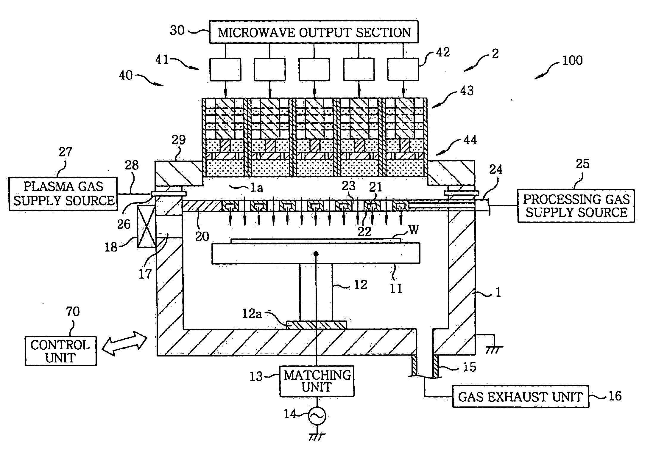
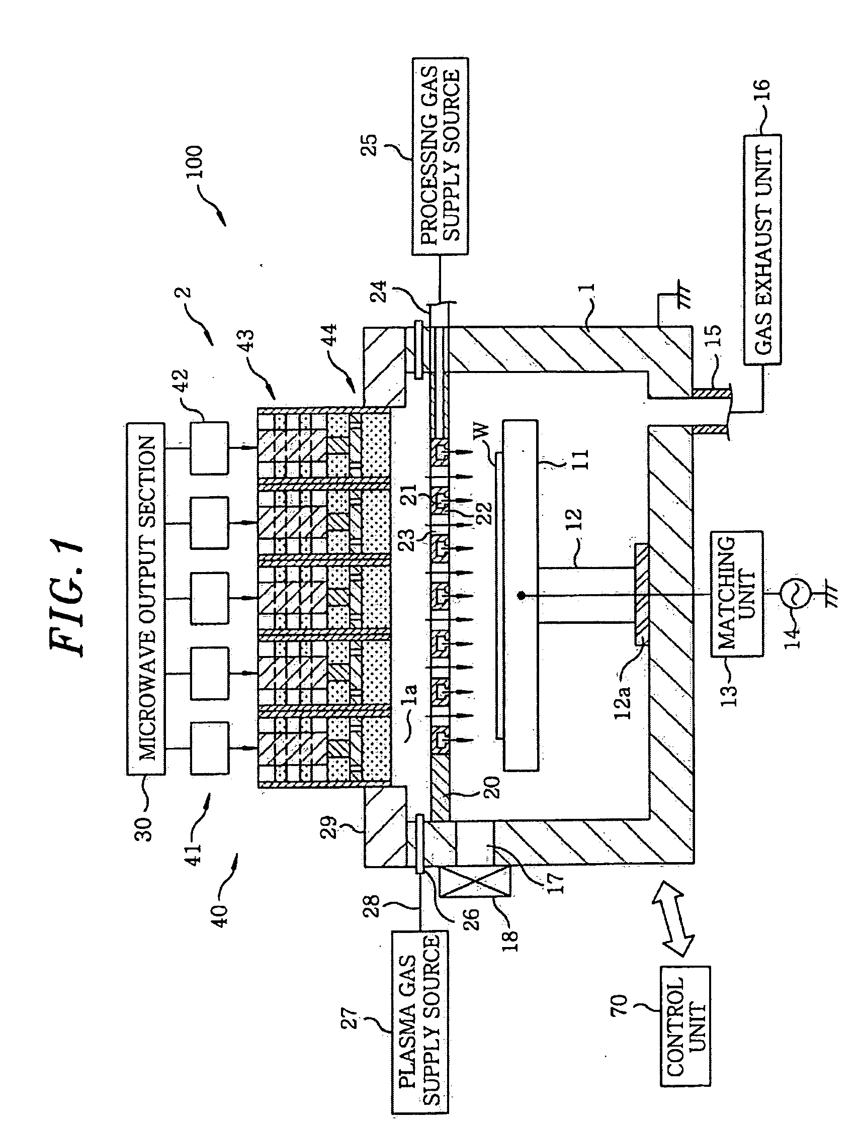
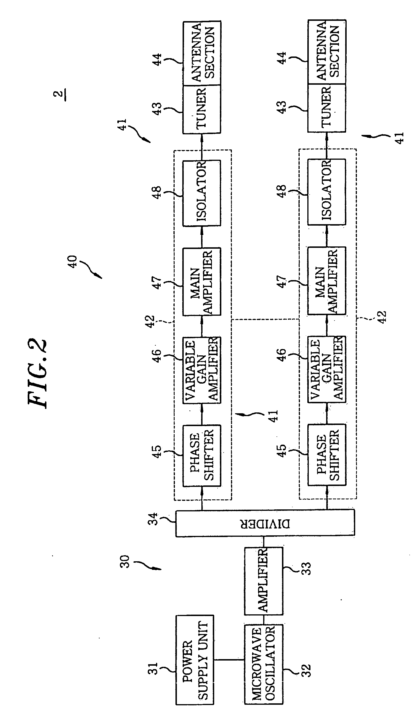
[0054]Embodiments of the present invention will be described with reference to the accompanying drawings. FIG. 1 is a cross sectional view showing a schematic configuration of a plasma processing apparatus having a microwave plasma source in accordance with an embodiment of the present invention; and FIG. 2 illustrates a configuration of the microwave plasma source in accordance with the embodiment of the present invention.

[0055]A plasma processing apparatus 100 is configured as a plasma etching apparatus for performing plasma processing, e.g., etching, on a wafer, and includes a substantially cylindrical airtight chamber 1 that is grounded and made of a metal material such as aluminum, stainless steel or the like and a microwave plasma source 2 for forming a microwave plasma in the chamber 1. An opening 1a is formed at an upper portion of the chamber 1, and the microwave plasma source 2 is installed toward the interior of the chamber 1 at the opening 1a.

[0056]A susceptor 11 for ho...


PUM

PropertyMeasurementUnit
frequencyaaaaaaaaaa
frequencyaaaaaaaaaa
frequencyaaaaaaaaaa

Abstract

A microwave plasma source (2) is provided with a microwave outputting section (30) which outputs plural divided microwaves, and a plurality of antenna modules (41) for guiding the plural divided microwaves into a chamber. Each antenna module (41) is provided with an amplifier section (42) having one or more amplifier (47) for amplifying a microwave, and an antenna section (44) having an antenna (51) for radiating the amplified microwave into the chamber, and a tuner (43) for adjusting impedance in a microwave transmission path. The tuner (43) is integrally arranged with the antenna section (44) to be located close to the amplifier (47).

Description

[0001]This application is a Continuation Application of PCT International Application No. PCT / JP2007 / 064345 filed on Jul. 20, 2007, which designated the United States.FIELD OF THE INVENTION[0002]The present invention relates to a microwave plasma source and a plasma processing apparatus using the same.BACKGROUND OF THE INVENTION[0003]In a manufacturing process of a semiconductor device or a liquid crystal display device, a plasma processing apparatus such as a plasma etching apparatus and a plasma CVD film forming apparatus has been employed to perform a plasma process, e.g., an etching process or a film forming process, on a substrate to be processed such as a semiconductor wafer, a glass substrate, and the like.[0004]There are well-known plasma generating methods used in the plasma processing apparatus, e.g., a method including steps of supplying a processing gas into a chamber with parallel plate electrodes disposed therein; feeding specific powers to the parallel plate electrode...

Claims


Application Information

Patent Timeline
Patent Type & Authority Applications(United States)
IPC IPC(8): H01L21/306C23C16/00C23F1/00B01J19/12
CPCH01J37/32192H05H1/46H01J37/32256H01J37/3222C23C16/511H01L21/205H01L21/3065
Inventor KASAI, SHIGERU
Owner TOKYO ELECTRON LTD
Why Eureka
Try Eureka