Positron emission tomography scanner and radiation detector

a tomography scanner and positron emission technology, applied in the field of positron emission tomography scanners and radiation detectors, can solve the problems of different output waveforms, different propagation path lengths, and radiation detection time presented errors, so as to reduce radiation detection time error, improve temporal resolution, and improve accuracy

Inactive Publication Date: 2009-06-25
NAT INST FOR QUANTUM & RADIOLOGICAL SCI & TECH
View PDF3 Cites 46 Cited by
  • Summary
  • Abstract
  • Description
  • Claims
  • Application Information

AI Technical Summary

Benefits of technology

[0020]The present invention was developed to address the aforementioned conventional problems. The invention relates to a technique, applied to a PET scanner, for determining the time of incidence of a radiation with improved accuracy. More particularly, an object of the present invention is to provide an improved signal to noise ratio and a spatial resolution for image reconstruction using time-of-flight difference.
[0023]In a radiation detector of the PET scanner, the combination of a scintillator crystal and an optical detector does not always have a one-to-one correspondence. Thus, in general, such a scanner holds data for estimating the coordinates of a light emitting crystal from the output signal(s) of an optical detector(s). As an example, in the prototype head scanner jPET-D4 developed by National Institute of Radiological Sciences in JAPAN, the data are referred to as the two-dimensional location histogram which provides a one-to-one correspondence between the information on a two-dimensional output location obtained from output signals through the anode electrodes of a photomultiplier tube used as an optical detector and an individual crystal in the three-dimensionally integrated crystal block. A look-up table having this location histogram stored in memory is referenced for each event to identify the crystal that has emitted light. Then, the data on the crystal coordinates and the time is sent to subsequent coincidence measurement and decision circuits. Here, such a mechanism may be added in which time error data is held in consistency with the look-up table of information on crystal coordinates or a look-up table prepared separately, and after the crystal is identified, reference is made to the time error data to rewrite the time. This would make it possible to realize a PET scanner that provides information regarding time-of-flight difference with improved accuracy.
[0024]The present invention was developed based on the results of those studies to provide a positron emission tomography scanner which employs information regarding the time-of-flight difference between annihilation radiations for image reconstruction. The scanner has detection time correction information corresponding to information on the coordinates, representing both the depth direction and the lateral direction (orthogonal to the depth direction), at which an interaction has occurred between an annihilation radiation and a radiation detection element. Reference is then made to the detection time correction information to provide information regarding time-of-flight difference with improved accuracy, thereby solving the aforementioned problems.
[0035]The present invention can be put into practice to reduce the error in radiation detection time and improve temporal resolution.
[0036]On the other hand, when a plurality of optical detectors are employed, even use of those having the same product type number would result in an error of about several tens of picoseconds due to variations in response property of individual optical detectors. Furthermore, even in the same optical detector, its central and peripheral portions often have different response properties, thereby causing an error in detection time. The coordinates at which a light emission phenomenon occurs due to an interaction between an annihilation radiation and a scintillator crystal, and correction time data corresponding to the coordinates are created. This means that a correction is to be made in consideration of the response property of one or more optical detectors at which the photons emitted at the coordinates arrive. It is thus possible to provide improved accuracy by simultaneous use of the coordinates in the lateral direction.

Problems solved by technology

The errors in detection time presented as problems are caused by the difference in propagation speed between an annihilation radiation and a scintillation light; the difference in propagation path length of scintillation light; and the difference in output waveform of an optical detector resulting from the difference in propagation path length of scintillation light.

Method used


Image

  • Positron emission tomography scanner and radiation detector
  • Positron emission tomography scanner and radiation detector
  • Positron emission tomography scanner and radiation detector

Examples


Embodiment Construction

[0047]Embodiments of the present invention will now be described in more detail with reference to the drawings.

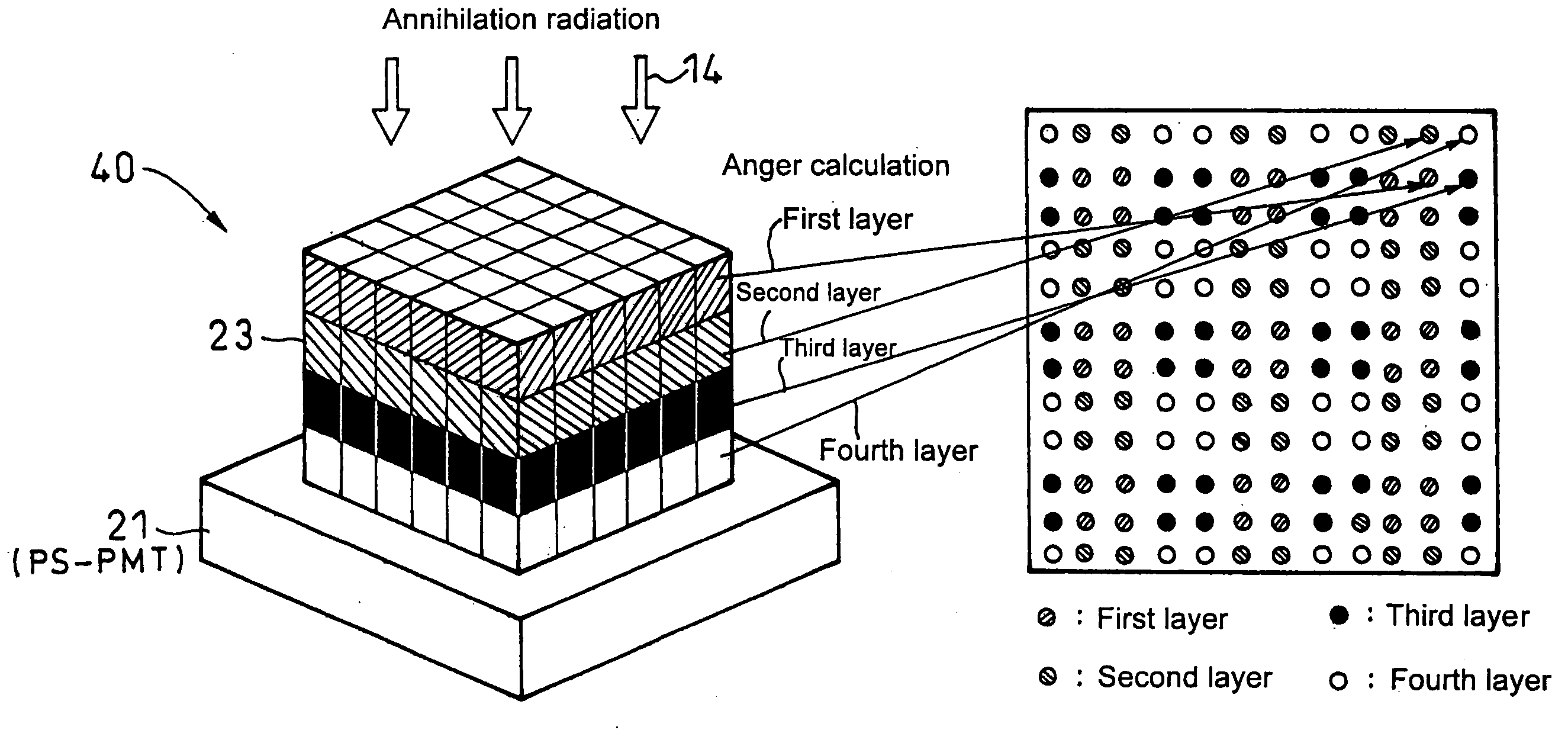
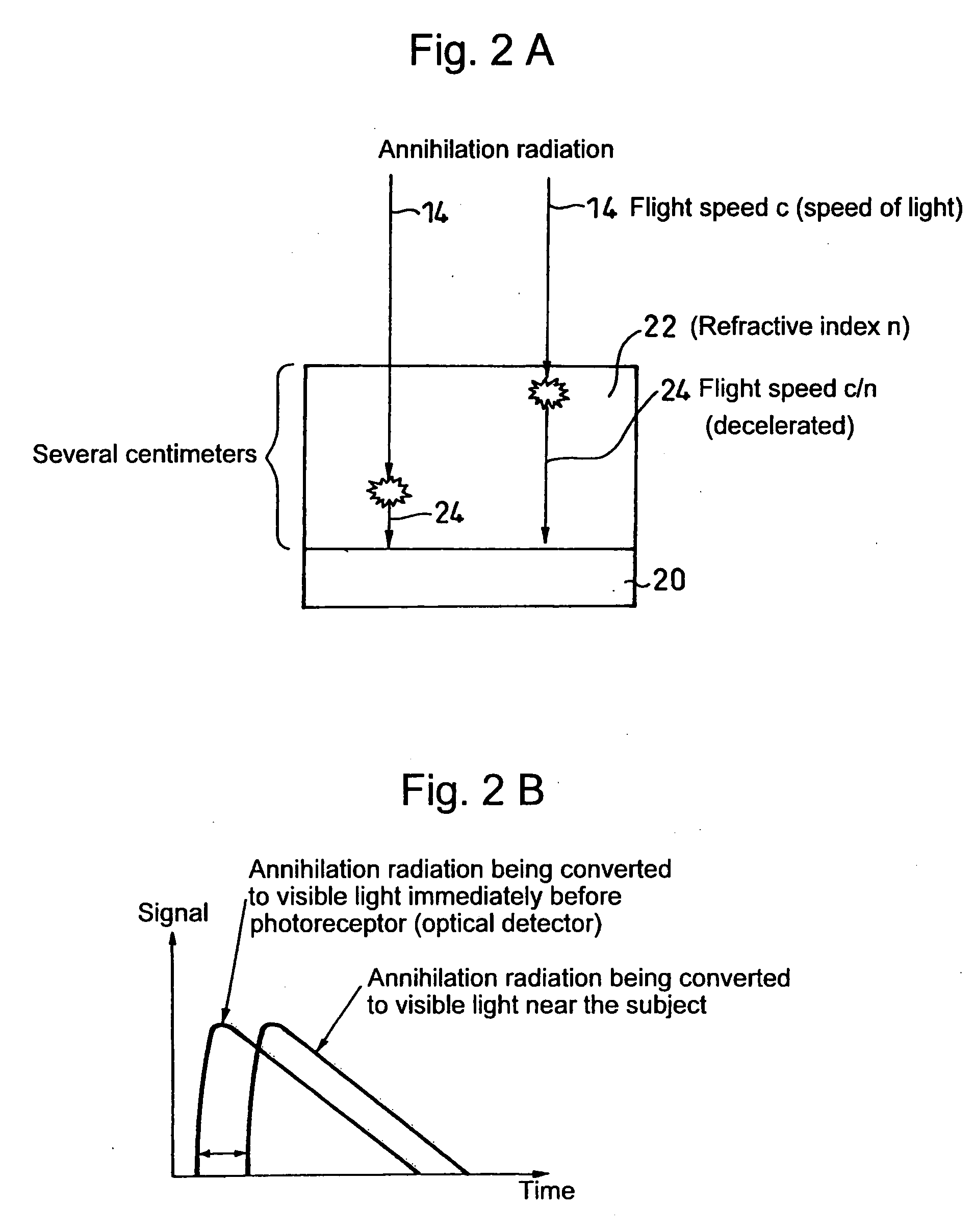
[0048]First, with reference to FIG. 7, described by way of example is a method for preparing data to be held to make a correction to errors in detection time. These errors in detection time include those caused by the difference in propagation speed between an annihilation radiation and scintillation light; the difference in propagation path length of scintillation light; and the difference in output waveform of an optical detector resulting from the difference in propagation path of scintillation light.

[0049]In FIG. 8, reference numeral 30 denotes a radiation source which employs a positron emitter like 22Na. Also reference numeral 32 denotes a radiation detector for measuring one of a pair of annihilation radiations of 511 keV to create a signal serving as a time reference. The radiation detector 32 includes a high-speed optical detector such as Type H3378 photomultiplier...


PUM


Abstract

A positron emission tomography (PET) scanner is provided which uses information on the time-of-flight difference (TOF) between annihilation radiations for image reconstruction. The scanner has detection time correction information (memory) corresponding to information on coordinates in a radiation detection element (e.g., scintillator crystal), in the depth and lateral directions, at which an interaction has occurred between an annihilation radiation and the crystal. Reference is made to the detection time correction information, thereby providing information on time-of-flight difference with improved accuracy. As such, an improved signal to noise ratio and spatial resolution are provided for image reconstruction using time-of-flight (TOF) difference.

Description

TECHNICAL FIELD[0001]The present invention relates to a positron emission tomography (PET) scanner which uses information on the time-of-flight difference between the two annihilation radiations for image reconstruction, and to a radiation detector. More particularly, the invention relates to a positron emission tomography scanner which can determine the time of incidence of each radiation with improved accuracy, and a radiation detector which can be used therefore in a preferred manner.BACKGROUND ART[0002]The positron emission tomography scanner is a nuclear diagnostic imaging system which utilizes a positron emitter and finds widespread applications such as cancer diagnosis or molecular imaging.[0003]A positron emitter is an isotope, such as 18F, which is unstable because of excess number of protons in the atomic nucleus against the number of neutrons, and which undergoes +β decay to emit a positron and a neutrino. The positron thus emitted is the antimatter counterpart of the ele...

Claims


Application Information

Patent Timeline
Patent Type & Authority Applications(United States)
IPC IPC(8): G01T1/164
CPCA61B6/037G01T1/2985
Inventor SHIBUYA, KENGOTSUDA, TOMOAKINISHIKIDO, FUMIHIKOINADAMA, NAOKOYOSHIDA, EIJIYAMAYA, TAIGAMURAYAMA, HIDEO
Owner NAT INST FOR QUANTUM & RADIOLOGICAL SCI & TECH
Why Eureka
Try Eureka