
Regeneration of Sulfur-Poisoned Noble Metal Catalysts in the Fuel Processing System for a Fuel Cell

Inactive Publication Date: 2009-06-25
ZHU TIANLI +1
View PDF3 Cites 10 Cited by
  • Summary
  • Abstract
  • Description
  • Claims
  • Application Information

AI Technical Summary

Benefits of technology

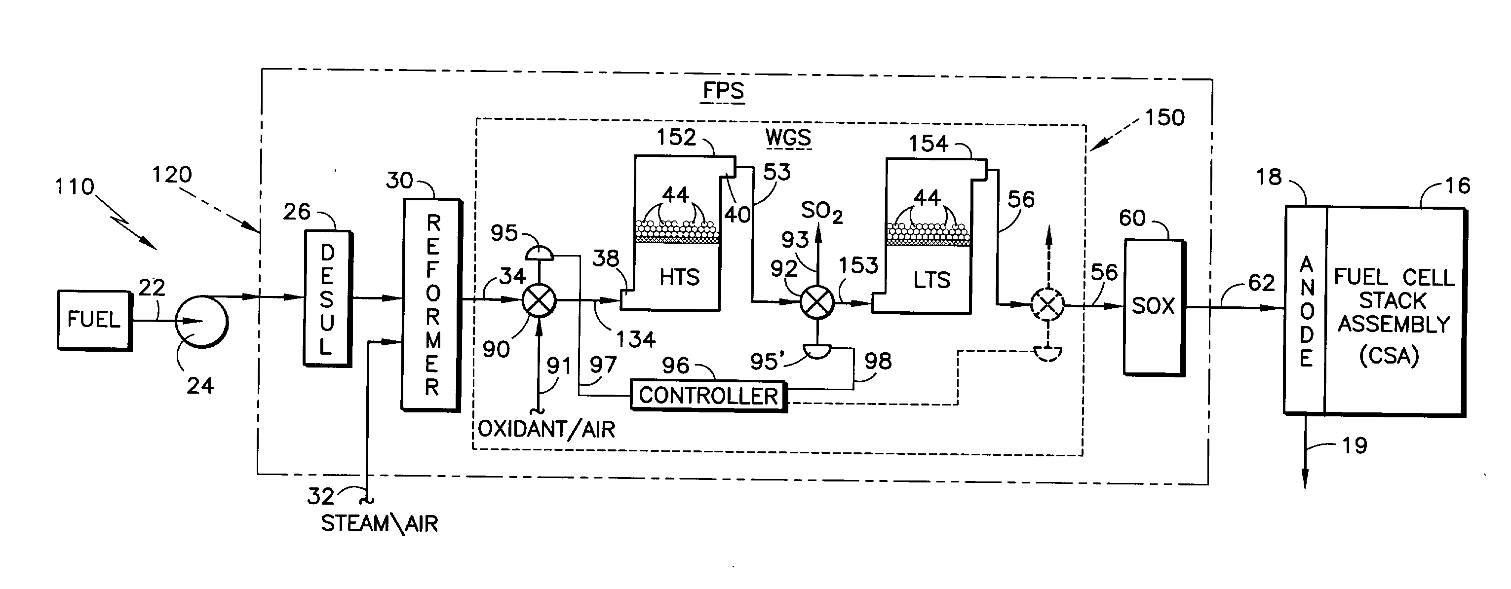
[0021]The present invention addresses the problem of even low levels of sulfur in the reformate entering the water gas shift reactor(s), and other sensitive catalyst-containing components downstream thereof, in a relatively more remedial than preventative manner, though it is preventative with respect to significant degradation of catalyst performance. According to the present invention, there is provided a technique and equipment for regenerating a potentially sulfur-burdened, noble metal catalyst and / or catalyst support in a water gas shift reactor, and possibly other sensitive catalyst-containing components downstream thereof, such as a selective oxidizer and the fuel cell stack itself, to minimize continued degradation of the catalyst performance and restore prior performance levels.
[0022]It has been recognized that the addition of oxygen, typically in the form of air, to sulfur-burdened, noble metal catalysts in an appropriate thermal environment, will effect an oxidation reaction with the sulfur to create SO2, a gas, which may then be removed from the system. Similarly, the addition of O2 will also effect an oxidation reaction with sulfides formed on catalyst supports such as ceria and the like, to create easily removed SO2.
[0023]In accordance with the invention, provision is made for the selective introduction of an oxidant, such as air, to at least the water gas shift reactor(s) for oxidizing the sulfur-burdened catalyst and / or support to form SO2. The noble metal and / or support is / are thereby regenerated, and the SO2 is removed from the immediate system, as by venting away from the fuel processing system and the fuel cell stack assembly. This / these oxidation reactions typically require an elevated temperature and are preferably conducted during an interval when reformate is not being reacted in the water gas shift reactor(s), so as to avoid release of SO2 downstream in the system and / or the exhaust venting of H2. Accordingly, the oxidant is introduced to the reactor(s) preferably at or soon after the shutting-down process in order to make use of the residual elevated temperatures in the reactor and catalyst bed. The resulting SO2 is similarly vented at that time. Appropriate valves, and timed control of those valves, provide an effective means to accomplish this end.

Problems solved by technology

Anode electrodes, which form part of the fuel cell stack, can be burdened or “poisoned” by a high level of carbon monoxide.
However, the raw hydrocarbon fuel source and / or even the air supplied to certain types of reformers, may also contain sulfur compounds, and hydrogen generation in the presence of sulfur results in a poisoning effect on all of the catalysts used in the hydrogen generation system, as well as the fuel cell anode catalyst itself.
As also noted above, the ambient air supplied to certain types of reformers may also contain objectionable amounts of sulfur.
Thus, depending upon what, if any, sulfur abatement measures are taken with respect to both the fuel and air paths in undergoing reformation, particularly with an ATR, there often remains a sulfur content in the reformate that is objectionably high.
The presence of sulfur in the reformate, even in reduced levels, accumulates on and ultimately “poisons” the noble metal catalysts downstream thereof, resulting in increasingly degraded performance.
This “poisoning” may occur as the result of H2S adsorbing on or forming sulfides with, the catalyst which then block active sites, and / or also through the agglomeration of the noble metal catalyst which also results in a decrease in activity.

Method used


Image

  • Regeneration of Sulfur-Poisoned Noble Metal Catalysts in the Fuel Processing System for a Fuel Cell
  • Regeneration of Sulfur-Poisoned Noble Metal Catalysts in the Fuel Processing System for a Fuel Cell

Examples


Embodiment Construction

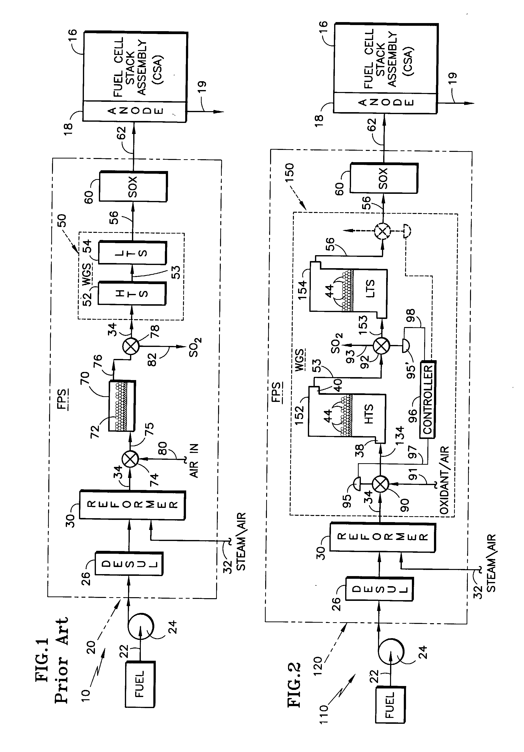
[0028]Realizing that a relatively thorough description of a representative fuel cell power plant was undertaken with respect to the description of FIG. 1 prior art, the following description of the invention with reference to FIG. 2 will “piggy-back” on that description of FIG. 1. Referring to FIG. 2, the elements that are essentially the same as their counterparts in FIG. 1 are given the same reference numeral as in FIG. 1, whereas those elements that are functionally similar but include some change in accordance with the invention, are similarly numbered but with a “1” prefix. Added elements are given new numbers. In FIG. 2, there is illustrated a fuel cell power plant 110 similar to that depicted in FIG. 1 with respect to the prior art, but differing principally in that it includes a fuel processing system (FPS) 120 with an improved arrangement for addressing the potential adverse impact of sulfur on sensitive catalysts and / or catalyst supports in accordance with the invention. T...


PUM


Abstract

A technique and equipment are provided for regenerating a potentially sulfur-burdened, noble metal catalyst (44) in a water gas shift reactor (150, 152, 154), which may be part of a fuel processing system (120) for a fuel cell power plant (110). An oxidant (91) is supplied to the reactor and catalyst during a period when the water gas shift reaction is terminated, and sulfur entities burdening the catalyst undergo an oxidation reaction to become SO2. The SO2 is then vented outside the system containing the reactor, as to the ambient. The oxidation reaction preferably occurs immediately upon the shift reaction being terminated to take advantage of the residual heat associated with the water gas shift reaction. Oxidant is conveniently admitted to the shift reactor and SO2 is vented from the reactor by appropriately-controlled valving that may work in combined alternation with the normal flow of process fuel through the shift reactor and fuel processing system.

Description

TECHNICAL FIELD[0001]This invention relates to fuel processing for fuel cells, and more particularly to the provision of a low-sulfur, hydrogen-rich fuel stream for a fuel cell. More particularly still, the invention relates to the regeneration of sulfur-poisoned, noble metal catalysts in a fuel processing system for a fuel cell power plant.BACKGROUND ART[0002]Fuel cell power plants that utilize a fuel cell stack for producing electricity from a hydrocarbon fuel source are well known. The raw hydrocarbon fuel may be natural gas, gasoline, diesel fuel, naphtha, fuel oil, or the like. In order for the hydrocarbon fuel to be useful in the fuel cell stack's operation, it must first be converted to a hydrogen-rich fuel stream through use of a fuel processing system. Such hydrocarbon fuels are typically passed through a reforming process (reformer) to create a process fuel (reformate) having an increased hydrogen content that is introduced into the fuel cell stack. The resultant process f...

Claims


Application Information

Patent Timeline
IPC IPC(8): H01M8/06H01M8/04B01J7/00C01B3/32
CPCB01J2219/00006C01B3/16C01B3/34C01B3/48C01B2203/0211C01B2203/0288Y02E60/50C01B2203/10C01B2203/127C01B2203/1642H01M8/0618H01M8/0631H01M8/0675C01B2203/066
Inventor ZHU, TIANLILESIEUR, ROGER R.
Owner ZHU TIANLI
Learn More