Fault Injection In Dynamic Random Access Memory Modules For Performing Built-In Self-Tests

a dynamic random access memory and self-testing technology, applied in error detection/correction, instruments, digital storage, etc., can solve the problems of complex and sometimes expensive memory subsystems of compute systems, high testing costs, and complex devices in computer systems

Active Publication Date: 2009-06-25
LENOVO GLOBAL TECH INT LTD
View PDF19 Cites 32 Cited by
  • Summary
  • Abstract
  • Description
  • Claims
  • Application Information

AI Technical Summary

Problems solved by technology

Since that time, computer systems have evolved into extremely complicated devices.
Compute systems today have complex and sometimes expensive memory subsystems.
Such a testing procedure is expensive, in terms of both time and money, because the test is manually administered and because the tested DRAM module cannot be put into production but must be discarded.

Method used


Image

  • Fault Injection In Dynamic Random Access Memory Modules For Performing Built-In Self-Tests
  • Fault Injection In Dynamic Random Access Memory Modules For Performing Built-In Self-Tests
  • Fault Injection In Dynamic Random Access Memory Modules For Performing Built-In Self-Tests

Examples


Embodiment Construction

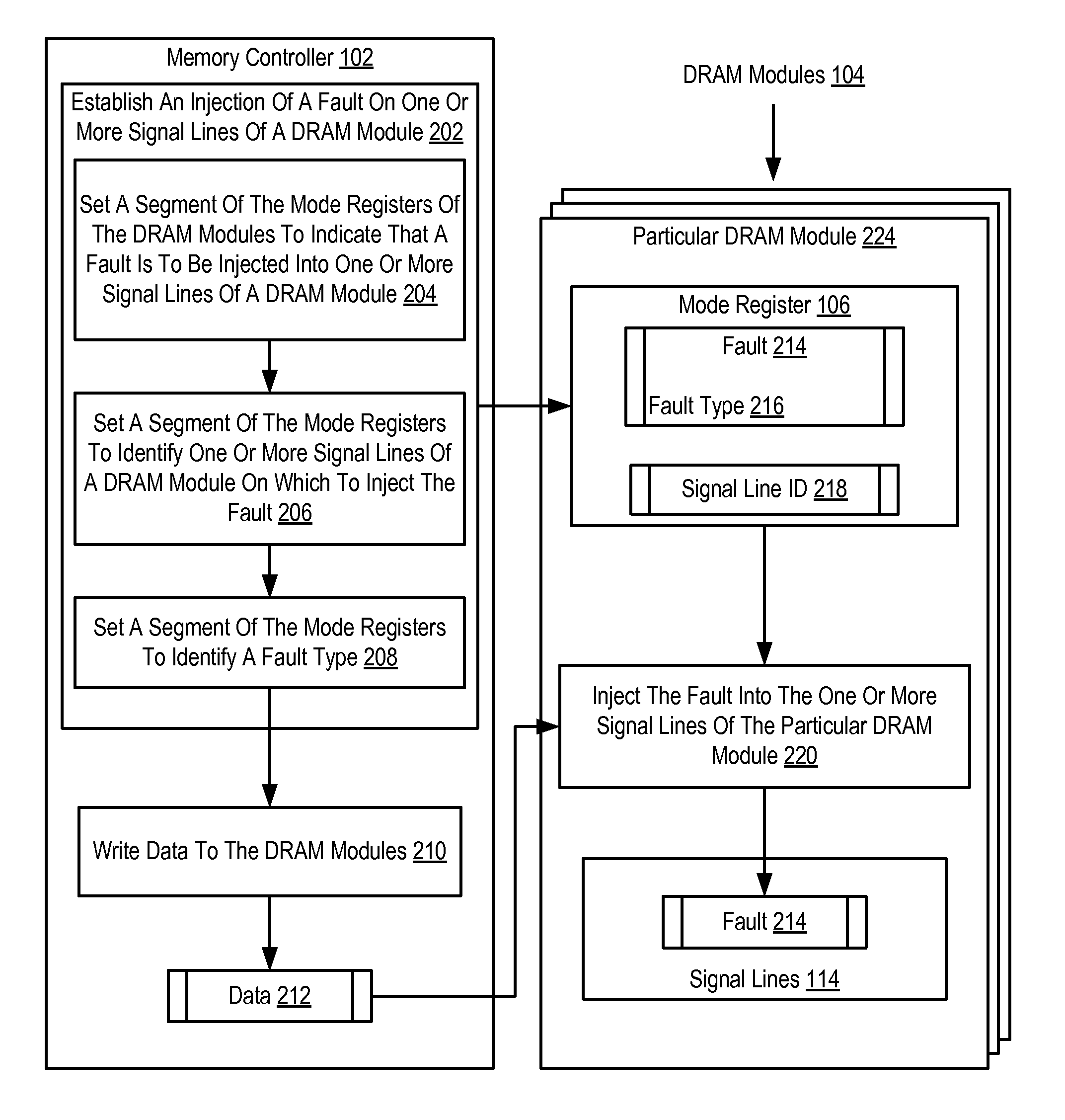
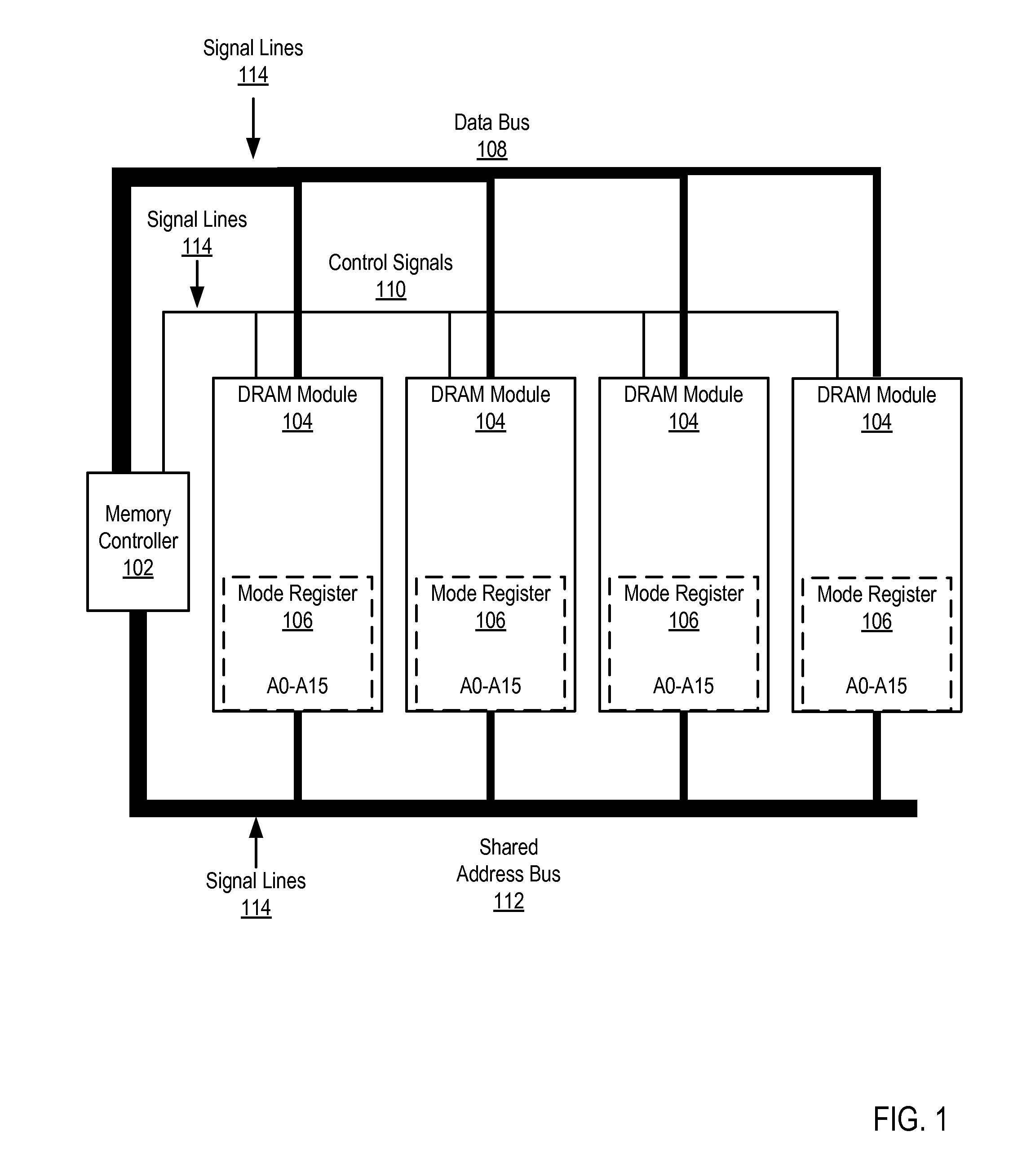
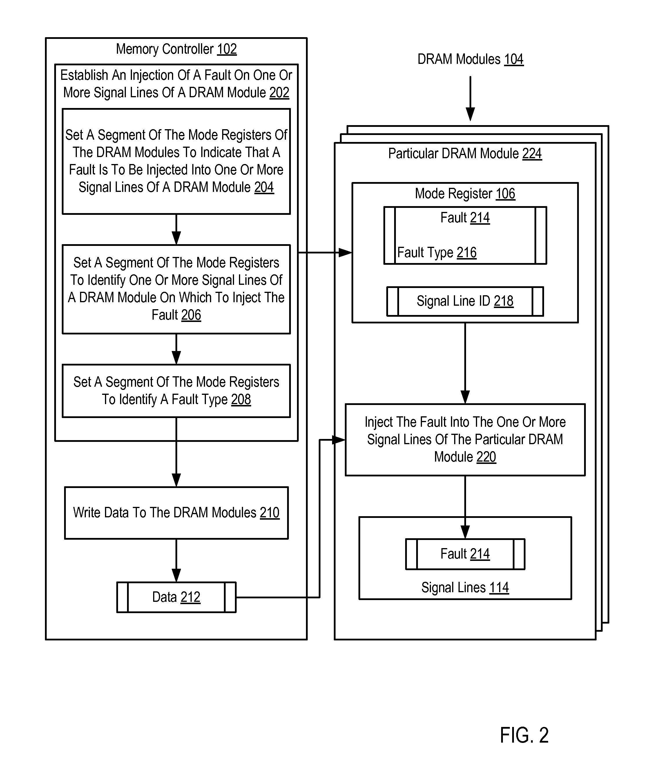
[0011]Exemplary dynamic access memory modules, apparatus, and products for fault injection in dynamic random access memory (‘DRAM’) modules for performing built-in self-tests (‘BISTs’) in accordance with the present invention are described with reference to the accompanying drawings, beginning with FIG. 1. FIG. 1 sets forth a functional block diagram of a system for fault injection in DRAM modules for performing BISTs. A BIST mechanism within an integrated circuit, in this case within a DRAM module, is a function that verifies all or a portion of the internal functionality of the integrated circuit. The main purpose of BISTs is to reduce the complexity, and thereby decrease cost and reduce reliance upon, external test equipment for integrated circuits. The DRAM modules of FIG. 1 may execute a BIST after a fault is injected into one or more signal lines of the DRAM module.

[0012]The system of FIG. 1 includes a memory controller (102), an aggregation of hardware and firmware, which man...


PUM


Abstract

Fault injection in dynamic random access memory (‘DRAM’) modules for performing built-in self-tests (‘BISTs’) including establishing, in the mode registers of the DRAM modules by the memory controller through the shared address bus, an injection of a fault into one or more signal lines of a DRAM module, the fault characterized by a fault type; writing data by the memory controller through a data bus to the DRAM modules, the data identifying a particular DRAM module; and responsive to receiving the data, injecting, by the particular DRAM module, the fault characterized by the fault type into the one or more signal lines of the particular DRAM module.

Description

BACKGROUND OF THE INVENTION[0001]1. Field of the Invention[0002]The field of the invention is data processing, or, more specifically, dynamic random access memory (‘DRAM’) modules, methods, and apparatus, for fault injection for performing built-in self-tests (‘BISTs’).[0003]2. Description of Related Art[0004]The development of the EDVAC computer system of 1948 is often cited as the beginning of the computer era. Since that time, computer systems have evolved into extremely complicated devices. Today's computers are much more sophisticated than early systems such as the EDVAC. Computer systems typically include a combination of hardware and software components, application programs, operating systems, processors, buses, memory, input / output devices, and so on. As advances in semiconductor processing and computer architecture push the performance of the computer higher and higher, more sophisticated computer software has evolved to take advantage of the higher performance of the hard...

Claims


Application Information

Patent Timeline
Patent Type & Authority Applications(United States)
IPC IPC(8): G06F11/00G06F11/07
CPCG11C5/04G11C11/401G11C29/02G11C29/022G11C29/56008G11C29/025G11C29/16G11C29/44G11C29/024
Inventor FOSTER, SR., JIMMY G.GRUENDLER, NICKOLAUS J.MICHELICH, SUZANNE M.TAYLOR, JACQUES B.
Owner LENOVO GLOBAL TECH INT LTD
Why Eureka
Try Eureka