Method and apparatus for manufacturing electrode assembly for rectangular battery

a manufacturing method and rectangular battery technology, applied in the direction of wound/folded electrode electrodes, sustainable manufacturing/processing, final product manufacturing, etc., can solve the problems of reducing the productivity reducing the efficiency difficulty in ensuring the positional performance of the positive and negative electrodes, etc., to achieve accurate manufacturing of the electrode assembly, short takt time, and high performance

Active Publication Date: 2009-07-02
ELIIY POWER
View PDF4 Cites 32 Cited by
  • Summary
  • Abstract
  • Description
  • Claims
  • Application Information

AI Technical Summary

Benefits of technology

[0023]The present invention was conceived in consideration of the circumstances encountered in the prior art mentioned above, and hence, an object of the present invention is to provide method of and apparatus for accurately manufacturing an electrode assembly for a rectangular battery or cell with high performance and with short takt time.

Problems solved by technology

In the laminate-method of the above (1), however, it is difficult to ensure the positional performance of the positive and negative electrodes and the separator, and in an adverse case in which their positions are shifted, the positive and negative electrodes may be short-circuited.
When precise positional arrangement is made to prevent such short-circuiting, it may result in delay of takt time manufacturing speed per one electrode assembly), which may result in reduction of productivity of the electrode assembly, i.e., batteries.
In the wind-up method of the above (2), if the electrode assembly is wound up in too many turns, a space between the electrode assembly and a corner portion of a battery case may provide a dead space and electric capacity may be reduced, thus providing a problem.
This operation makes delay the takt time, which results in reduction of productivity, thus providing a problem.
Furthermore, in this zigzag-stack method, since it is intended to fold the separator in zigzag form on curved surfaces of the rollers, it is difficult to accurately fold the separator in the zigzag form and, hence, the separator, i.e., the electrode assembly, likely become warped, which may result in deterioration of performance of the battery.
In addition, when the separator is folded in the zigzag form, the separator is moved in a meandering manner and, hence, is not accurately folded.
In the technology disclosed in the above Patent Document 2, it is intended to form the electrode assembly by clamping the continuous separator in the zigzag form between the hard positive electrode and negative electrode held with a constant interval, so that it may pose a problem such that the separator is likely broken by a large tension (load) applied to the separator, and in a case that the electrode is thin and soft, its manufacture is made difficult, thus also providing a problem.
In such method, the takt time is elongated and it is difficult to enhance the productivity.
Therefore, in this manufacturing method, the zigzag-folding of the electrode assembly is made fine and the electric capacity is hence reduced, thus providing a problem.
In addition, both the positive and negative electrodes are mutually contacted at certain positions, so that the positive electrodes and the negative electrodes may include portions not contributing to power generation, thus also providing a problem

Method used


Image

  • Method and apparatus for manufacturing electrode assembly for rectangular battery
  • Method and apparatus for manufacturing electrode assembly for rectangular battery
  • Method and apparatus for manufacturing electrode assembly for rectangular battery

Examples


first embodiment

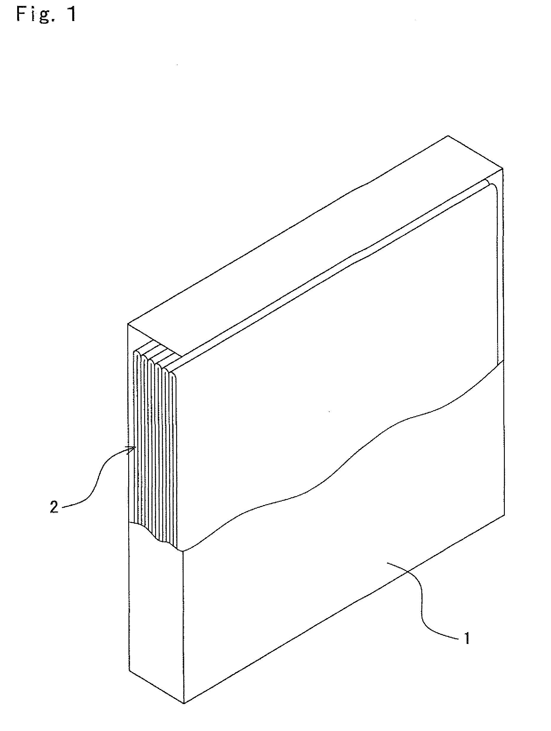
[0158]With reference to FIG. 1, reference numeral 1 denotes a rectangular case of a lithium ion secondary battery, reference numeral 2 denotes an electrode assembly accommodated in the rectangular case 1. Positive terminal and negative terminal, both not shown, are provided at predetermined positions of the rectangular case 1. Electrolyte formed by combining organic solvent with lithium salt fills in the rectangular case 1.

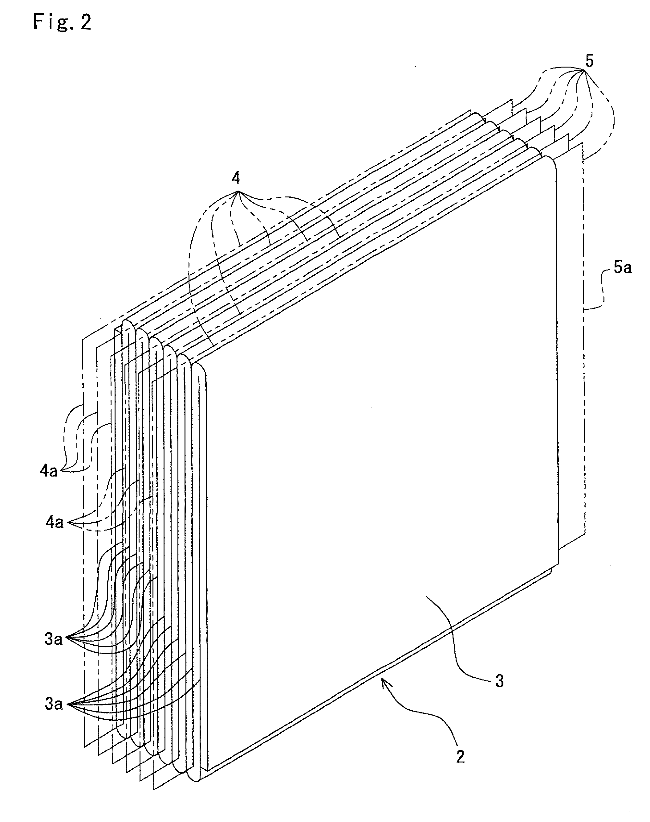
[0159]The electrode assembly 2 is formed, as shown in FIG. 2, as a laminated structure including a continuous member 3 of separator formed in zigzag form (which may be called separator continuous member 3 or merely continuous member 3, hereinlater), and positive electrodes 4 and negative electrodes 5 alternately inserted respectively into valley grooves 3a of the continuous member 3. Further, it is to be noted that the term “valley grooves 3a” used herein are portions of the continuous member 3 of the separator which are formed by folded (bent) bottom portions in ...

second embodiment

[0201]As shown in FIG. 9, an electrode assembly 22 according to this second embodiment includes a laminated member composed of a continuous member 23 folded in zigzag form and the positive electrodes 4 inserted into valley grooves 3a of the continuous laminated member 23, respectively. The continuous laminated member 23 is a laminated member composed of two rows of continuous members 3, 3 of the separators and a continuous negative electrode 24 interposed between the two rows of the separators. According to this structure, the positive electrodes 4 inserted into the respective valley grooves 23a of the continuous laminated member 23 oppose to the continuous negative electrode 24 with the separator being interposed therebetween. The positive electrodes 4 and the continuous negative electrode 24 are provided with lead portions 4a and 24a which are projected from the separator in opposing directions, and these lead portions 4a and 24a are bundled respectively, which are then connected ...

third embodiment

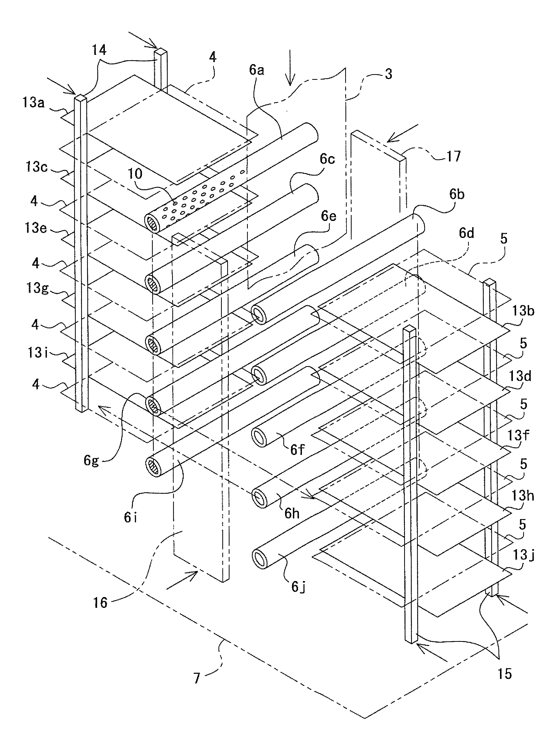
[0205]In the third embodiment, as shown in FIG. 12, a link mechanism 25 is utilized as the pitch changing mechanism for narrowing the interval between the rows of the guide rods 6a, 6b, 6c, 6d, 6e, 6f, 6g, 6h, 6i and 6j in the perpendicular direction.

[0206]This link mechanism is a parallel motion mechanism including a plurality of members each pivoting links 25a, 25a having the same length so as to provide an X-shape, which are connected by means of pins in perpendicular direction. A shaft 26 of the guide rods 6a, 6c, 6e, 6g and 6i is inserted into each pivot point of the X-shaped paired links 25a, 25a, and one end of each of the shafts 26 is inserted into a guide groove 27a of a guide member 27 extending in the perpendicular direction. In order to easily hold horizontally the guide rods 6a, 6c, 6e, 6g and 6i, a plurality of link mechanisms may be arranged in rows as occasion demands.

[0207]Though not shown, substantially identical arrangements of the link mechanisms and guide member...


PUM

PropertyMeasurementUnit
timeaaaaaaaaaa
timeaaaaaaaaaa
takt timeaaaaaaaaaa

Abstract

In a method of manufacturing an electrode assembly for a rectangular battery, in which positive electrodes and negative electrodes are alternately laminated so that a separator exists between the respective positive and negative electrodes, the manufacturing method includes the steps of: arranging a plurality of guide members in zigzag form in a perpendicular direction; inserting a continuous member of the separator between one and another one rows of the guide members; folding, into zigzag form, the continuous member by intersecting the rows of the guide members in a horizontal direction; inserting alternately the positive electrodes and the negative electrodes in respective valley grooves of the zigzag-folded continuous member; withdrawing the guide members from the respective valley grooves of the continuous member; and pressing, thereafter, the continuous member in the zigzag direction so as to make flat the continuous member.

Description

BACKGROUND OF THE INVENTION[0001]1. Field of the Invention[0002]The present invention relates to method of and apparatus for manufacturing an electrode assembly adapted for a battery having a rectangular structure, called “rectangular battery” hereinlater.[0003]2. Related Art[0004]An electrode assembly in a battery such as lithium ion secondary battery or cell is formed by alternately laminating positive electrodes and negative electrodes with a separator being disposed between a positive electrode and a negative electrode. Such electrode assembly may be manufactured by the following typical methods.[0005](1) Laminate Method: a separator, a positive electrode and a negative electrode, which are all formed in shape of sheet, are laminated such that the separator is disposed between the positive electrode and the negative electrode (for example, refer to the following Patent Document 5)[0006](2) Wind-up Method: a separator, a positive electrode and a negative electrode, which are all ...

Claims


Application Information

Patent Timeline
Patent Type & Authority Applications(United States)
IPC IPC(8): B32B38/00H01M50/466
CPCB32B38/1808B32B2457/10H01M2/18Y10T29/49108H01M10/049Y02E60/12Y10T156/1051H01M10/0431Y10T29/53139Y02E60/10Y02P70/50H01M50/466H01M10/0409H01M10/0459
Inventor SAKATA, TAKUYAYOSHIDA, AYUMISATO, HIROSHI
Owner ELIIY POWER
Why Eureka
Try Eureka