
Composition for anisotropic pigmented film, anisotropic pigmented film, and polarizing element

a technology anisotropic pigmented film, which is applied in the direction of polarizing elements, instruments, chemistry apparatuses and processes, etc., can solve the problems of low dichroism, degrade the polarizing performance of anisotropic pigmented film, and lack of heat resistance and light resistance, etc., to achieve high dichroism, high uniformity, and high productivity

Inactive Publication Date: 2009-07-02
MITSUBISHI CHEM CORP
View PDF5 Cites 6 Cited by
  • Summary
  • Abstract
  • Description
  • Claims
  • Application Information

AI Technical Summary

Benefits of technology

[0015]The object of the present invention is to provide a composition for an anisotropic dye film that can be used to form an anisotropic dye film having a high dichroism and a high uniformity in a coating film at a high productivity, as well as a high-dichroism anisotropic dye film formed using such a composition for an anisotropic dye film and a polarizing device formed using such an anisotropic dye film.

Problems solved by technology

When used in a polarizing plate, however, iodine has been lacking in heat resistance and light resistance and posed a problem that the polarizing performance thereof is degraded over time, because of the strong tendency thereof to sublime.
However, such known dichroic dye films have posed a problem of low dichroism.
This reduction in dichroism has been caused not only by the Schlieren defect inherent in liquid crystals described in those documents, but also by light leakage due to defects or cracks on a film originating in dry distortion at the time of drying an applied coating in the process of forming such a dye film in a wet film-forming process.
The foregoing facts have been making it difficult to achieve a balance among the high uniformity in a coating film, a high productivity and a high dichroism in the process of forming an anisotropic dye film.

Method used


Image

  • Composition for anisotropic pigmented film, anisotropic pigmented film, and polarizing element
  • Composition for anisotropic pigmented film, anisotropic pigmented film, and polarizing element
  • Composition for anisotropic pigmented film, anisotropic pigmented film, and polarizing element

Examples


example 1

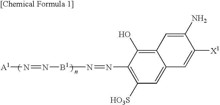
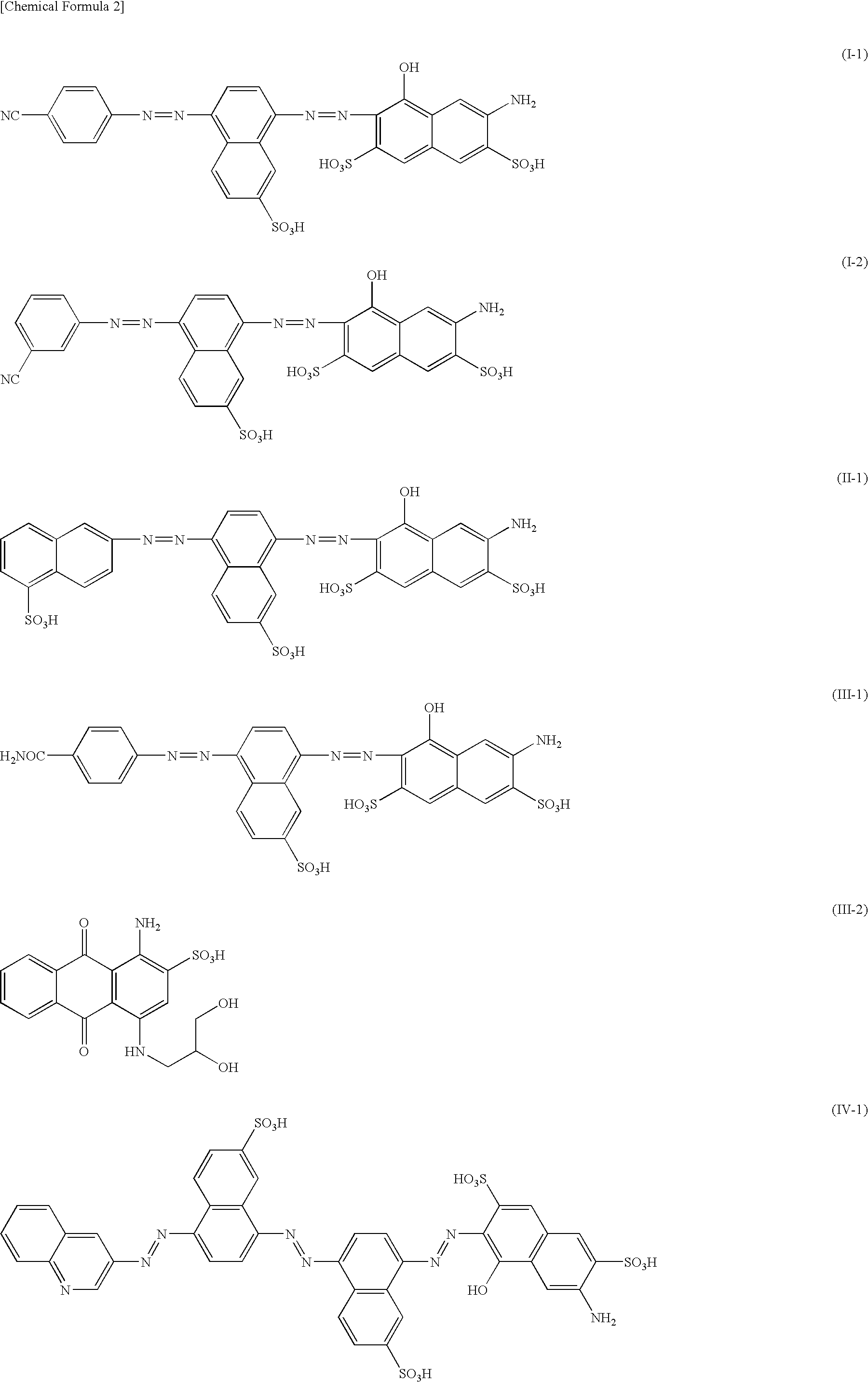
[0154]The composition for an anisotropic dye film was obtained by adding 20 parts of the lithium salt of the abovementioned Dye No. (I-1) into 80 parts of water, stirring the mixture until the salt was dissolved, and then filtering the resulting solution.

[0155]In this composition for an anisotropic dye film, the relaxation modulus G measured 0.01 seconds after the application of strain at a temperature of 5° C. using the abovementioned method was 9.2×101 dyn / cm2, and the time until the relaxation modulus G dropped to 1 / 10 was 0.04 seconds, i.e., shorter than 0.1 seconds.

[0156]This composition for an anisotropic dye film was applied using an applicator with a gap set at 2 μm (a four-sided applicator manufactured by IMOTO MACHINERY Co., Ltd.) on a substrate, which had been prepared by coating a glass plate (75 mm×25 mm, 1 mm thick) with an oriented polyimide film (approximately 800 Å thick) in a serigraphic method and rubbing the product using a cloth, and then dried in vacuum. In thi...

example 2

[0158]The composition for an anisotropic dye film was obtained by adding 30 parts of the lithium salt of the abovementioned Dye No. (II-1) and 1 part of 4,5,6-triaminopyrimidine sulfate (manufactured by Tokyo Chemical Industry Co., Ltd.) into 69 parts of water, stirring the mixture until the added substances was dissolved, and then filtering the resulting solution.

[0159]In this composition for an anisotropic dye film, the relaxation modulus G measured 0.01 seconds after the application of strain at a temperature of 5° C. using the abovementioned method was 1.8×10⁴ dyn / cm2, and the time until the relaxation modulus G dropped to 1 / 10 was 0.05 seconds, i.e., shorter than 0.1 seconds.

[0160]This composition for an anisotropic dye film was applied in the same procedures as those for Example 1 on the same kind of a substrate as that used in Example 1, providing the anisotropic dye film.

[0161]The obtained anisotropic dye film had neither defects nor cracks, and the dichroic ratio measured a...

example 3

[0162]The composition for an anisotropic dye film was obtained by adding 15 parts of the lithium salt of purified Dye No. (I-1) mentioned above, 5 parts of the salt of the abovementioned Dye No. (I-1) formed by neutralization with lithium atoms to an extent of 80 mol %, 1 part of purified Alizarin Red S manufactured by Aldrich, and 0.06 parts of lithium chloride into 78.94 parts of water, stirring the mixture until the added substances was dissolved, and then filtering the resulting solution.

[0163]In this composition for an anisotropic dye film, the relaxation modulus G measured 0.01 seconds after the application of strain at a temperature of 5° C. using the abovementioned method was 9.9×101 dyn / cm2, and the time until the relaxation modulus G dropped to 1 / 10 was 0.04 seconds, i.e., shorter than 0.1 seconds.

[0164]This composition for an anisotropic dye film was applied in the same procedures as those for Example 1 on the same kind of a substrate as that used in Example 1, providing ...


PUM

PropertyMeasurementUnit
temperatureaaaaaaaaaa
Temperatureaaaaaaaaaa
diameteraaaaaaaaaa

Abstract

An anisotropic dye film that exhibits a high dichroism and a high uniformity in a coating film is formed at a high level of productivity. In the composition for an anisotropic dye film containing a dye and being capable of forming a lyotropic liquid crystal phase, the time until the relaxation modulus G measured 0.01 seconds after the application of strain drops to 1 / 10 is equal to or shorter than 0.1 seconds at a temperature of 5° C. The composition contains a cation and a strongly acidic anion that respectively account for contents in the range of 0.9 to 0.99 equivalence and in the range of 0.02 to 0.1 equivalence relative to the content of the acidic groups of the dye. An anisotropic dye film is formed using this composition for an anisotropic dye film. A polarizing element is formed using this anisotropic dye film.

Description

FIELD OF THE INVENTION[0001]The present invention relates to a composition for an anisotropic dye film that can be used to form an anisotropic dye film having a high dichroism and being useful as a polarizing film or the like included in an indicating element of a light control device, a liquid crystal device (LCD), and an organic electroluminescent device (OLED), as well as an anisotropic dye film formed using such a composition for an anisotropic dye film and a polarizing device formed using such an anisotropic dye film.BACKGROUND OF THE INVENTION[0002]In an LCD, a linearly polarizing plate or a circularly polarizing plate is used to control the optical rotation and birefringence in display. Also in an OLED, a circularly polarizing plate is used to avoid reflection of external light. Such polarizing plates (polarizing elements) have conventionally used iodine as a dichroic material. When used in a polarizing plate, however, iodine has been lacking in heat resistance and light resi...

Claims


Application Information

Patent Timeline
Patent Type & Authority Applications(United States)
IPC IPC(8): C09K19/52
CPCC09K19/02G02B5/3016C09K19/60G02B5/30G02F1/1335
Inventor HASEGAWA, RYUICHISANO, HIDEOOIZUMI, JUNICHIKADOWAKI, MASAMI
Owner MITSUBISHI CHEM CORP
Learn More