Eureka AIR delivers breakthrough ideas for toughest innovation challenges, trusted by R&D personnel around the world.

Process for Production of Polytetrafluoroethylene Sheet, and Process for Production of Polytetrafluoroethylene Seal Tape

Inactive Publication Date: 2009-07-02
NITTO DENKO CORP
View PDF17 Cites 5 Cited by
  • Summary
  • Abstract
  • Description
  • Claims
  • Application Information

AI Technical Summary

Benefits of technology

[0011]As described, it has been difficult conventionally to form a PTFE sheet directly and continuously from a starting material containing PTFE particles. This has placed limitations on improving productivity. It is accordingly an object of the present invention to provide a manufacturing method of a PTFE sheet and a manufacturing method of a PTFE seal tape, that are more productive than conventional methods and less expensive in terms of the cost of production.
[0012]A method of manufacturing a PTFE sheet according to the present invention includes: (i) applying such a force to a PTFE particle dispersion containing PTFE particles, a surfactant, and water as a dispersion medium, that the particles approach or make contact with each other to form a PTFE-containing solid material including the water and the surfactant; (ii) deforming the solid material into a sheet form; and (iii) reducing a content of the water in the solid material deformed into a sheet form.
[0013]A method of manufacturing a PTFE seal tape according to the present invention includes: (i) applying such a force to a polytetrafluoroethylene particle dispersion containing polytetrafluoroethylene particles, a surfactant, and water as a dispersion medium, that the particles approach or make contact with each other to form a polytetrafluoroethylene-containing solid material including the water and the surfactant; (ii) deforming the solid material into a sheet form; and (iii) reducing a content of the water in the solid material deformed into a sheet form.
[0014]According to the present invention, a PTFE-containing solid material, moldable into a sheet form, can be obtained directly from a dispersion of PTFE particles. That is, the invention enables continuous production of a PTFE sheet or a PTFE seal tape from the starting material dispersion. A manufacturing method of the present invention is therefore more productive than traditional manufacturing methods of a PTFE sheet, and, since no organic solvents are used as forming aids, the method is more environmentally friendly than the traditional methods.

Problems solved by technology

As described, it has been difficult conventionally to form a PTFE sheet directly and continuously from a starting material containing PTFE particles.
This has placed limitations on improving productivity.

Method used


Image

  • Process for Production of Polytetrafluoroethylene Sheet, and Process for Production of Polytetrafluoroethylene Seal Tape
  • Process for Production of Polytetrafluoroethylene Sheet, and Process for Production of Polytetrafluoroethylene Seal Tape
  • Process for Production of Polytetrafluoroethylene Sheet, and Process for Production of Polytetrafluoroethylene Seal Tape

Examples


example 1

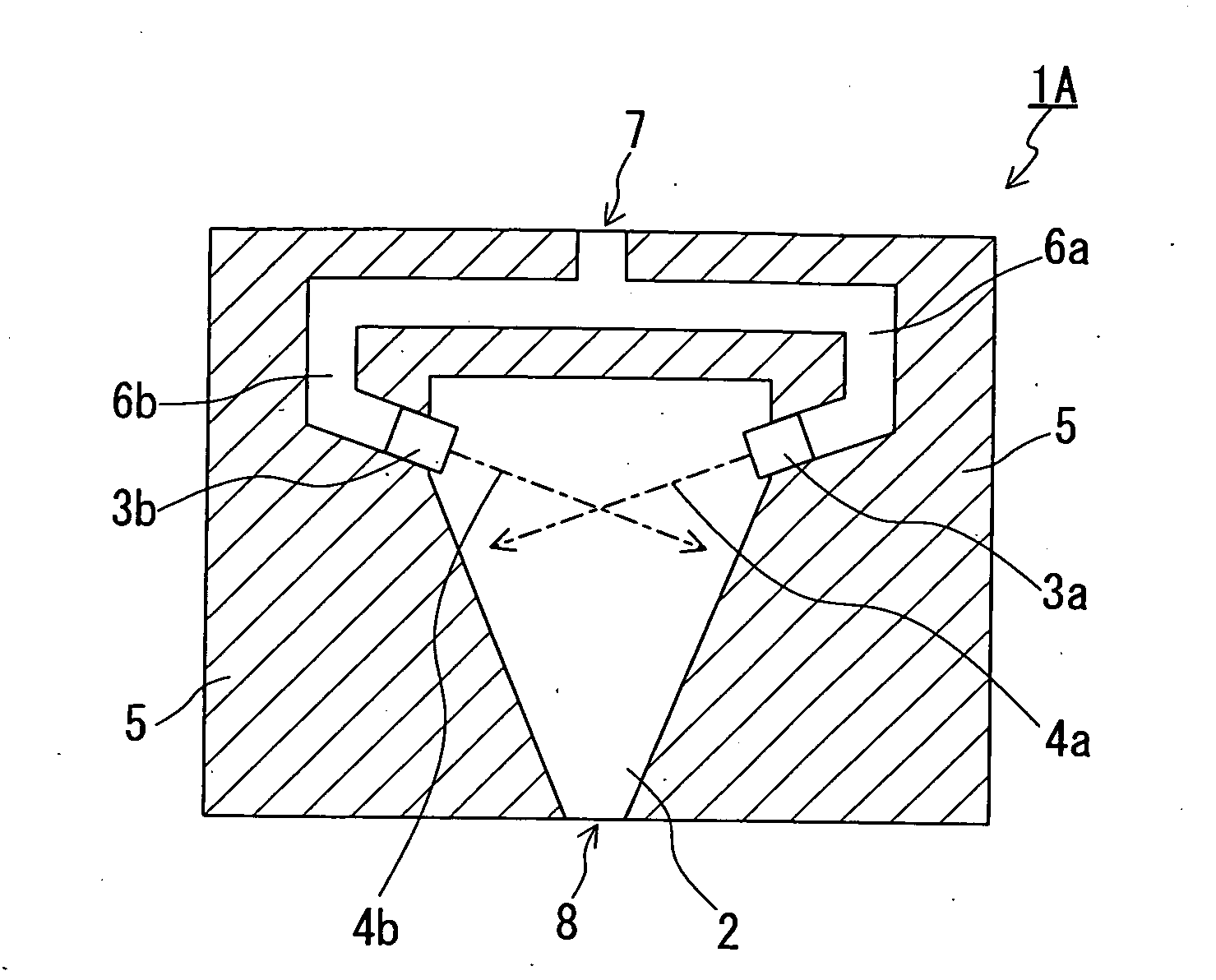
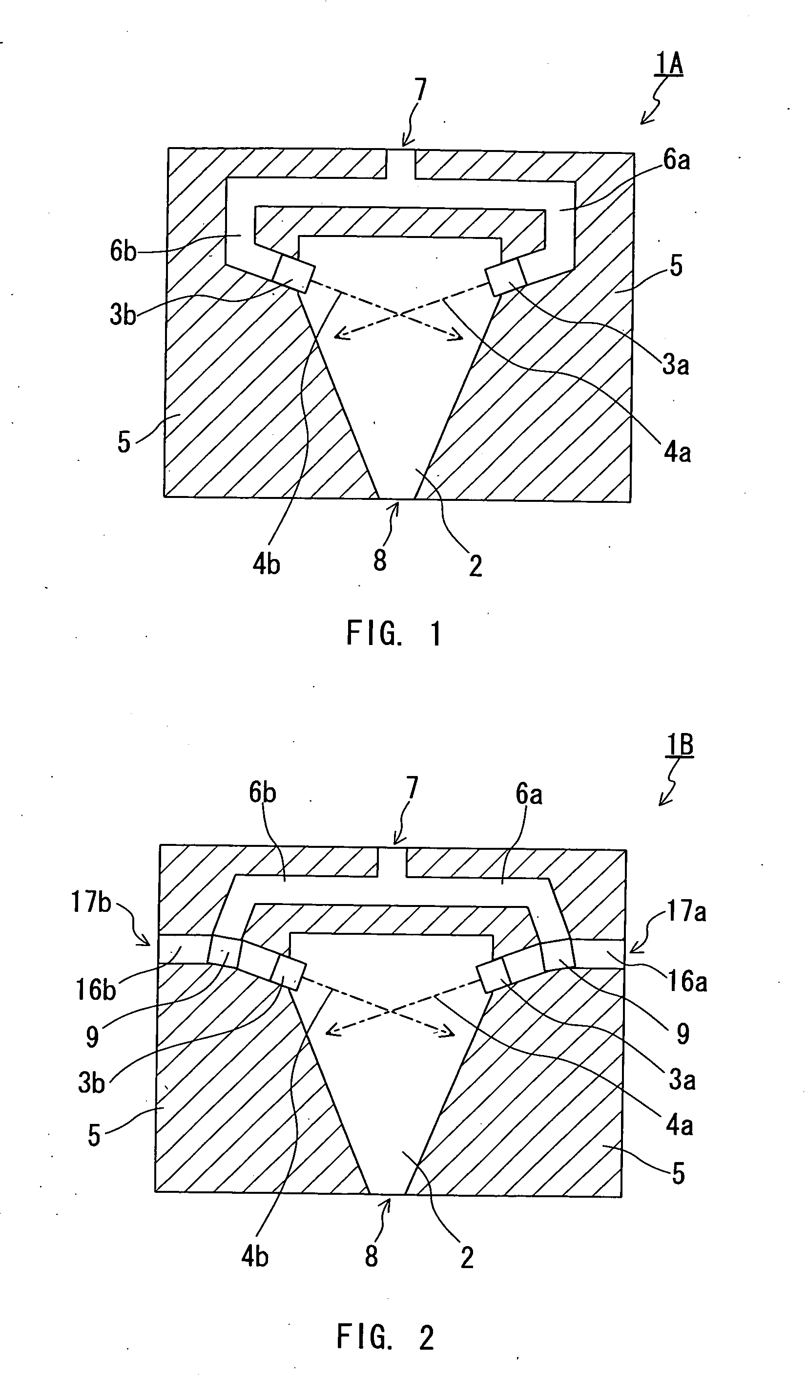
[0109]In Example 1, AD938 (the content of the PTFE particles: 60 mass %; the content of the surfactant: 3 mass %; average particle diameter of PTFE particles: 0.3 μm) manufactured by Asahi Glass Co., Ltd., a commercially available PTFE dispersion, was employed for the dispersion. A sheet-like solid material was formed with the chamber 1A shown in FIG. 1, and the formed sheet-like solid material was dried and fired to fabricate a PTFE sheet.

[0110]The volume of the inside space 2 of the chamber 1A (the inner volume of the chamber 1A) was 200 cm3, a pair of nozzles 3a and 3b was disposed in the chamber each having a circular spraying orifice (ø 0.25 mm). Diamond was used for the part where the spraying orifice was formed at the nozzle head, and the nozzles 3a and 3b were disposed to cross the respective spraying directions 4a and 4b of the nozzles with each other. The outlet 8 (in a circular form, diameter of 10 mm) was connected with a pipe (a first pipe) having a cross section in a c...

reference example 1

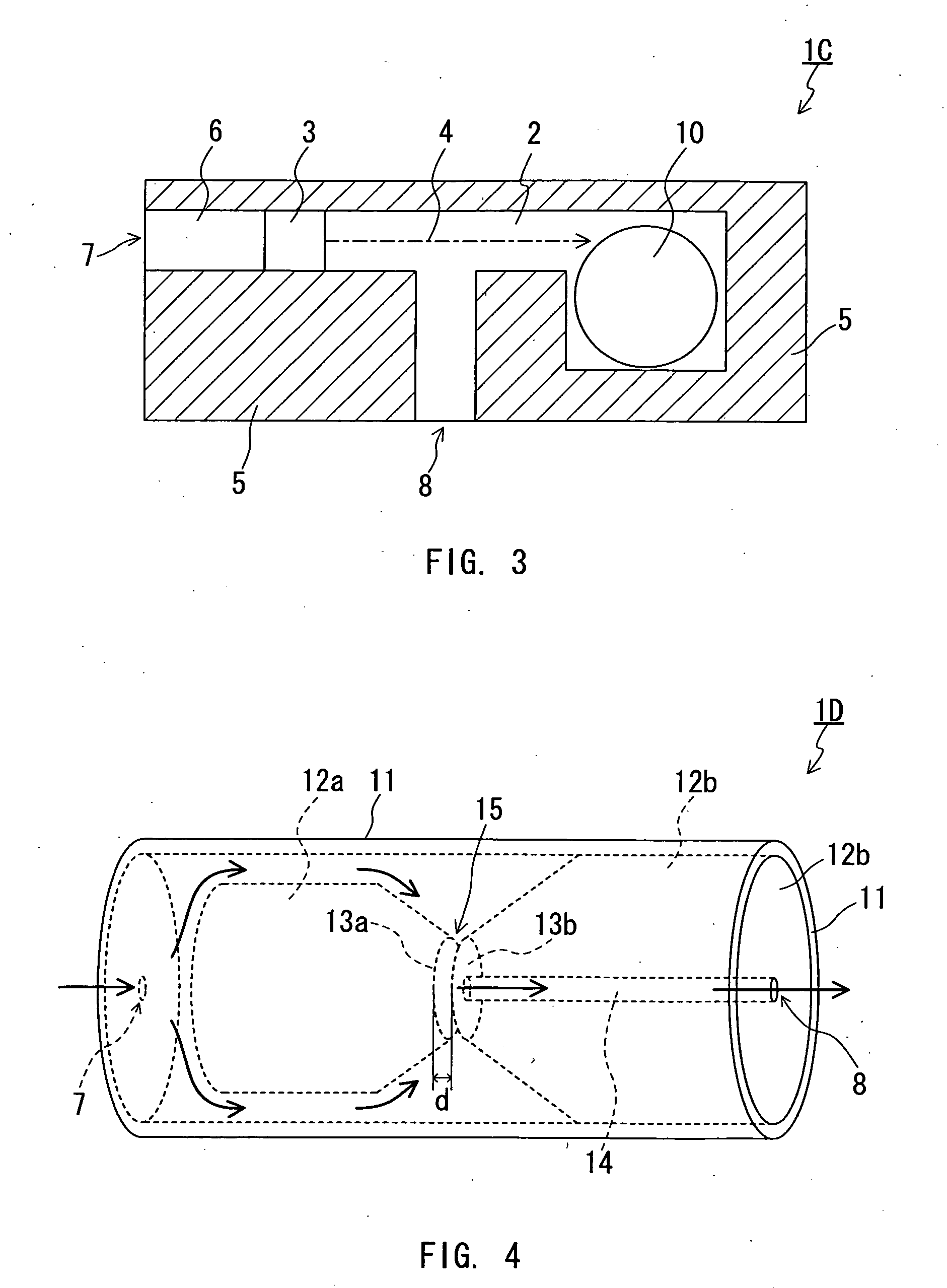
[0116]In Reference Example 1, AD938 manufactured by Asahi Glass Co., Ltd. was employed for the dispersion. A solid material in a string form was formed with the chamber 1D shown in FIG. 4, and the formed solid material was dried and fired to fabricate a PTFE product in a string form.

[0117]The inner volume of the chamber 1D was 200 cm3, and the interval d of the narrowed space in the form of a slit was 0.1 mm by controlling the location of the inner units 12a and 12b. The outlet 8 (in a circular form, 10 mm of diameter) was connected with a pipe (a first pipe) having the cross section in a circular form, the inner diameter of 1.6 mm and the length of 200 mm.

[0118]The dispersion pressurized at 245 MPa was supplied to the chamber 1D. The amount of the supplied dispersion was approximately 0.5 L / min and the temperature of the dispersion was 25° C. No heating was applied to the chamber 1.

[0119]Several seconds after the start of the supply of the dispersion, the PTFE-containing solid mate...

reference example 2

[0122]In Reference Example 2, AD938 manufactured by Asahi Glass Co., Ltd. was employed for the dispersion. A PTFE solid material in a string form was formed with a pipe (a second pipe) 21 shown in FIG. 8. The pipe 21 had a bent portion 23 in the form of the letter L near one end 22 of the pipe 21 as a barrier inhibiting the flow of the dispersion. The pipe 21 had the inner diameter of 10 mm and the length 200 mm, and the bent portion 23 was located at a distance of 30 mm from the end 22 of the pipe 21.

[0123]A nozzle 25 (having a circular spraying orifice (ø 0.15 mm)) disposed at the end of the feeder 26 for the dispersion was located on the central axis of the pipe 21 described above. The nozzle 25 and the pipe 21 were disposed so that the other end 24 of the pipe 21 and the nozzle 25 were 5 mm, distant from each other (refer to FIG. 8), and then the dispersion was sprayed inside the pipe 21 from the nozzle 25 at the spray pressure of 160 MPa. The amount of the dispersion supplied t...


PUM

PropertyMeasurementUnit
Temperatureaaaaaaaaaa
Forceaaaaaaaaaa
Dispersion potentialaaaaaaaaaa

Abstract

Disclosed is a process for production of a polytetrafluoroethylene (PTFE) sheet, which is superior in productivity compared to conventional processes and can reduce the cost of production. Also disclosed is a process for production of a PTFE seal tape. The processes comprise the following steps (i) to (iii): (i) applying a force to a PTFE particle suspension comprising PTFE particles, a surfactant and water (a dispersion medium) so that the particles can come close to each other or contact with each other, thereby forming a PTFE-containing solid material having the water and the surfactant included therein; (ii) shaping the solid material into a sheet-like form; and (iii) reducing the water content in the sheet-like solid material.

Description

TECHNICAL FIELD[0001]The present invention relates to a method of manufacturing a polytetrafluoroethylene (PTFE) sheet and a method of manufacturing a PTFE seal tape, both using a dispersion of PTFE particles as a starting material.BACKGROUND ART[0002]Since PTFE has properties such as high chemical resistance and low conductivity, a high melting point and excellent heat resistance, it is used for a variety of purposes mainly in chemical and electric fields. It is widely used for machinery purposes such as non-lubricated sliding components taking advantage of the property of a small friction coefficient or surface tension.[0003]One type of PTFE product is a sheet-like product (PTFE sheet), which finds many applications depending on its form, including shape and thickness. For example, a strip-like PTFE sheet with a thickness of about several ten to several hundred micrometers suitably can be used as a seal tape to create a seal at the joint of pipes such as water pipes and gas pipes....

Claims


Application Information

Patent Timeline
IPC IPC(8): C08J5/02C08J5/18B29C48/305
CPCB29C47/0004B29C47/0021B29C55/005C08J2327/18B29K2027/18B29K2105/256C08J5/18B29C67/06B29C48/022B29C48/08
Inventor WANO, TAKASHINAGAI, YOZOHORIE, YURITANAKA, ATSUSHITABEI, OSAMU
Owner NITTO DENKO CORP
Why Eureka
Eureka Blog
Learn More