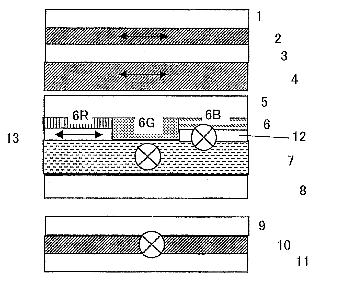
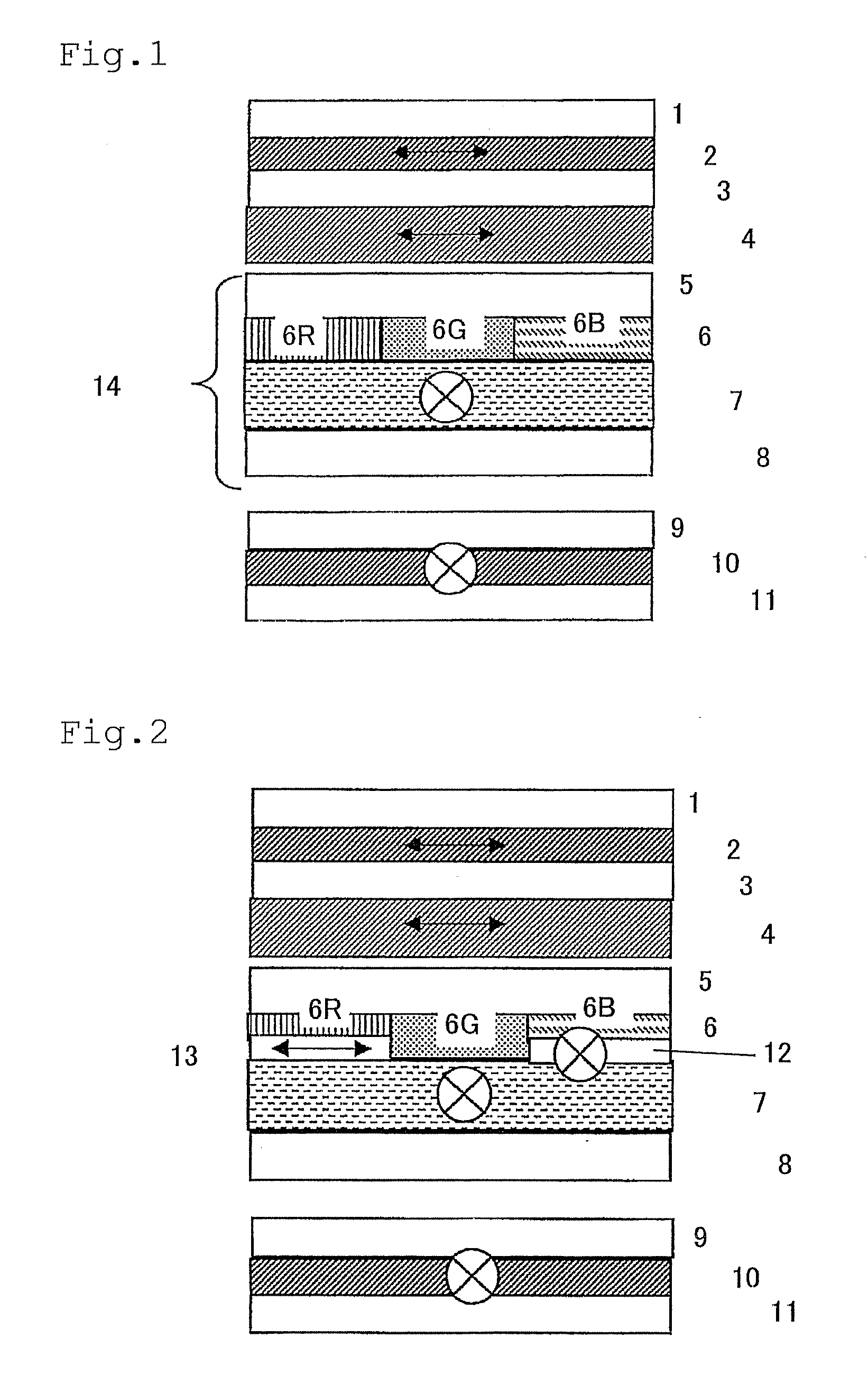
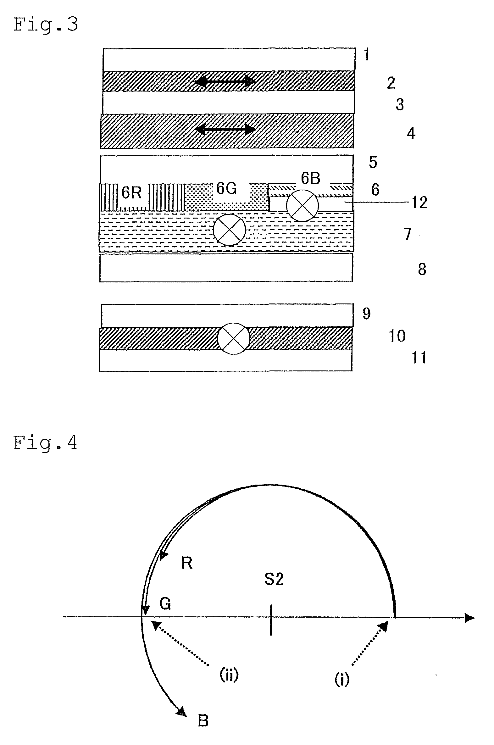
[0043]The invention is characterize by compensating individually for a light of wavelength that could not completely be compensated for by conventional constitution. For example, the constitution in FIG. 1 can completely compensate for G (6G), but can not completely compensate for wavelengths of R (6R) and B (6B). Therefore, these R (6R) and B (6B) are individually compensated for in addition. In FIG. 2, a constitutional example for describing the function of the invention is schematically shown. The constitution in FIG. 2 is a constitution in which, to the constitution in FIG. 1, a retardation layer 2 (12) being a second retardation film with Re of 72 nm and Rth of approximately 0 nm is arranged between the liquid crystal layer and B while intercrossing the slow phase axis perpendicularly to the retardation layer 1 (4), and, in addition, a retardation layer 3 (13) being a second retardation film with Re of 65 nm and Rth of approximately 0 nm is arranged between the liquid crystal layer and R (6R) so that the slow phase axis thereof is parallel to the retardation layer 1 (4). With help from the retardation layer 2 and the retardation layer 3, by previously pulling back the polarization state of B that will overrun the point (ii) in FIG. 4, and by previously advancing the polarization state that will not reach (ii) by passing through the retardation layer 1 (4), it is possible to match polarization states of R, G, B to (ii) after passing through the retardation layer 1. As the result, it is possible to improve significantly viewing angle contrast at black level, as well as to reduce significantly coloring in a viewing angle direction at black level. Here, as the wavelength of R, G, B, a wavelength λ=650 nm for R, a wavelength λ=550 nm for G, and a wavelength λ=450 nm for B were used. The wavelength of R, G, B is not always represented by these wavelengths, but they are thought to be appropriate wavelengths to show the effect of the invention.
[0044]FIG. 5 shows the polarization state of an oblique incident light having an azimuthal angle of 45° and a polar angle of 60° in the constitution of FIG. 2. Numerals in the drawing are common to those in FIG. 1 (same for FIG. 3). The polarization state of a light passed through the polarizing layer 2, the polarizing plate protective film 3, and the liquid crystal layer is indicated by the point (i). By passing through the retardation layer 2 and the retardation layer 3 having the aforementioned
optical property, B transits from the point (i) to (iB) in the drawing as shown by the lower arrow, G does not transit and remains at the point (i), and R transits from the point (i) to the point (iR) as shown by the upper arrow. After that, the light passes through the retardation layer 1 to be of the polarization state indicated by the point (R), point (G) and point (B) in the drawing just before the polarizing layer 1. Each of respective polarization states coincides approximately with the point (ii), and, as the result, it becomes possible to prevent the light pass-through approximately completely at any wavelengths of R, G, B. The above is described about the transition of the polarization state when light enters from the polarizing layer 2 side. The same effect can be obtained when the light enters from the polarizing layer 1 side.
[0045]In FIG. 3, another constitutional example for describing the function of the invention is schematically shown. The constitution in FIG. 3 is a constitution in which, in the constitution in FIG. 1, Re of the retardation layer 1 (4) is determined to 300 nm that can allow an approximately medium wavelength of R and G to come most closely to the point (ii), and, further, a retardation layer 2 (12) being the second retardation film having Re of about 105 nm and Rth of approximately 0 nm is arranged between a liquid crystal layer (7) and B so that the slow phase axis thereof is perpendicular to the retardation layer 1 (4). The polarization state of an oblique incident light with an azimuthal angle=45° and a polar angle=60° in this constitution is shown in FIG. 6. The polarization state of light passed through the polarizing layer 2, the polarizing plate protective film 3 and the liquid crystal layer is indicated by the point (i). As the result of passing through the retardation layer 2 having the aforementioned
optical property, B transits from the point (i) to the point (iB) in the drawing as shown by an arrow in a
clockwise direction, and G and R remain at (i) without transition. After that, the light passes through the retardation layer 1 to become a light of the polarization state shown by the point (R), point (G) and point (B) in the drawing just before the polarizing layer 1. Respective polarization states come close to the point (ii), making it possible to reduce the light pass-through at any wavelengths of R, G, B. As the result, the viewing angle contrast at black level is significantly improved, and, at the same time, coloring in a viewing angle direction at black level is significantly reduced. The above describes about the transition of the polarization state when light enters from the polarizing layer 2 side. The same effect can be obtained when the light enters from the polarizing layer 1 side.
[0046]In the invention, incomplete compensation that is attributable to wavelength dispersion of a commonly used first retardation film is corrected by a second retardation film only for a light whose compensation has been not complete, thus approximately complete compensation is effected in any wavelengths of R, G, B. In this system, it becomes possible to use even a retardation film which has a poor wavelength dispersion property and is not used generally, although inexpensive, as a first retardation film. In addition, since the second retardation film is a film for correcting shift based on the wavelength dispersion, it sufficiently functions with a very small retardation compared with the first retardation film. Therefore, compared with a conventional system of forming different retardation films for respective R, G, B, a significantly thin film thickness can be realized. Consequently, there is such characteristic that planarization is easily effected even when a retardation film is provided, according to such method as controlling the thickness of the color filter. In addition, needless to say, the system has such large
advantage that process number for forming additional compensation films can be decreased to ⅓ or ⅔ of a conventional system.
[0047]Here, the first retardation film functions so as to reduce light leakage caused by
anisotropy of
birefringence of liquid crystal in a liquid
crystal cell occurring in the direction of a polar angle of 60° and an azimuthal angle of 45° at the time of black level of a
liquid crystal display device, or shift of a polarizing axes crossing angle from orthogonality when orthogonal polarizing plates are viewed from an oblique direction. When the compensation is not performed, usually, although somewhat varying depending on
operation mode of liquid crystal, light leakage becomes large at this azimuthal angle in any
operation mode, and 0.5%-3.5% of linearly-polarized light entering a liquid
crystal display device leaks in the aforementioned light-observing direction to induce a large contrast lowering. The compensation by the first retardation film indicates reducing this light leakage, and, in the invention, an effect of reducing light leakage to one seventh or less, the light leakage being measured in the direction of a polar angle of 60° and an azimuthal angle of 45° with a single wavelength at the time of black level when a first retardation film is not used. On the other hand, “is not compensated for” indicates a state in which the light leakage falls with in a range of more than one seventh to the same amount as the case where no first retardation film is used.
[0048]According to the idea of the invention, as combinations of a wavelength for which the first retardation film (retardation layer 1) can completely compensate (a wavelength to be compensated for among any of B, G, R, medium of B and G, medium of G and R) and a retardation film adjacent to respective color filters, it is possible to apply plural systems as shown in Table 1. One of these systems is selected in accordance with
operation mode and compensation system of a liquid crystal, required properties of additional retardation films, and cost and performance target. As to the position of the first retardation film, although the inside and outside of a liquid
crystal cell can give the same effect of optical performance, it is preferred to form the same between a
cell and a polarizing plate from the viewpoint of
rework property and wideness of the selection range of material. On the other hand, as to the position of a second retardation film (retardation layer 2), it is preferred to form the same between the liquid crystal layer and the color filter, between the color filter and the substrate, or between driving electrodes and the substrate from the viewpoint of preventing lowering of compensation capability caused by
parallax. When parallel light is used as a backlight, the formation between the liquid crystal cell and the polarizing plate is possible.TABLE 1Necessary second retardation filmWavelength for which aTwo types of additionalTwo types of additionalOne type of additionalfirst retardation film canretardation
layers at tworetardation
layers at oneretardation layer at onecompletely compensatepositions in one pixelposition in one pixelposition in one pixelBDifferent retardation filmsIdentical retardationfor respective G and Rfilm for G and RGDifferent retardation filmsfor respective R and BRDifferent retardation filmsIdentical retardationfor respective G and Bfilm for B and GMedium of B & RRetardation filmfor R aloneMedium of G & RRetardation filmfor G alone

