Sound effect circuit and processing method

a processing method and circuit technology, applied in the field of sound effect circuit and processing method, can solve the problems of noise also giving unpleasantness to a person in the silence state, and achieve the effect of suppressing noise generation, suppressing noise generation, and not increasing the circuit scal

Active Publication Date: 2009-07-02
LAPIS SEMICON CO LTD
View PDF13 Cites 9 Cited by
  • Summary
  • Abstract
  • Description
  • Claims
  • Application Information

AI Technical Summary

Benefits of technology

[0007]An object of the present invention is to provide a sound effect circuit and processing method which can suppress generation of noise from the sound effect circuit in a silence state without increasing a circuit scale.
[0008]In accordance with an aspect of the present invention, the above and other objects can be accomplished by the provision of a sound effect circuit comprising: a digital sound effect unit configured to be supplied with an input audio signal and output an output signal which is generated with a sound effect in accordance with an effect amount of a certain value from the input audio signal; a silence state detection unit configured to be supplied with the input audio signal and output a silence detect signal which is generated when detecting that the current state of the input audio signal is a silence state; and a sound effect amount control unit configured to be supplied with the output signal and output an output audio signal, wherein the sound effect amount control unit changes the effect amount to be smaller than the certain value when the silence detect signal is generated. In accordance with another aspect of the

Problems solved by technology

However, the configurations disclosed in the above documents are basically techniques relating to a volume control circuit such as an amplifier or the like, w

Method used


Image

  • Sound effect circuit and processing method
  • Sound effect circuit and processing method
  • Sound effect circuit and processing method

Examples


first embodiment

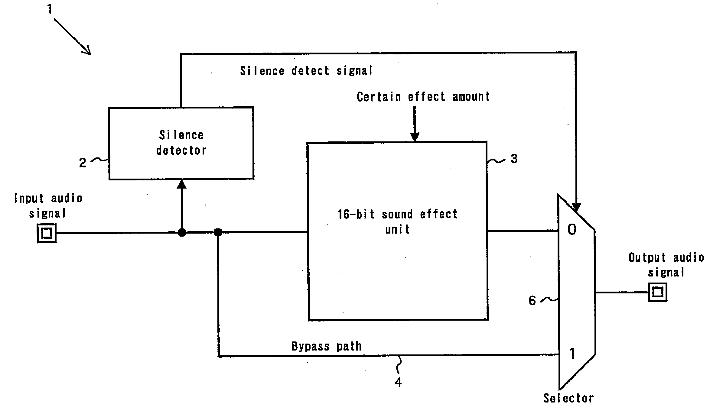
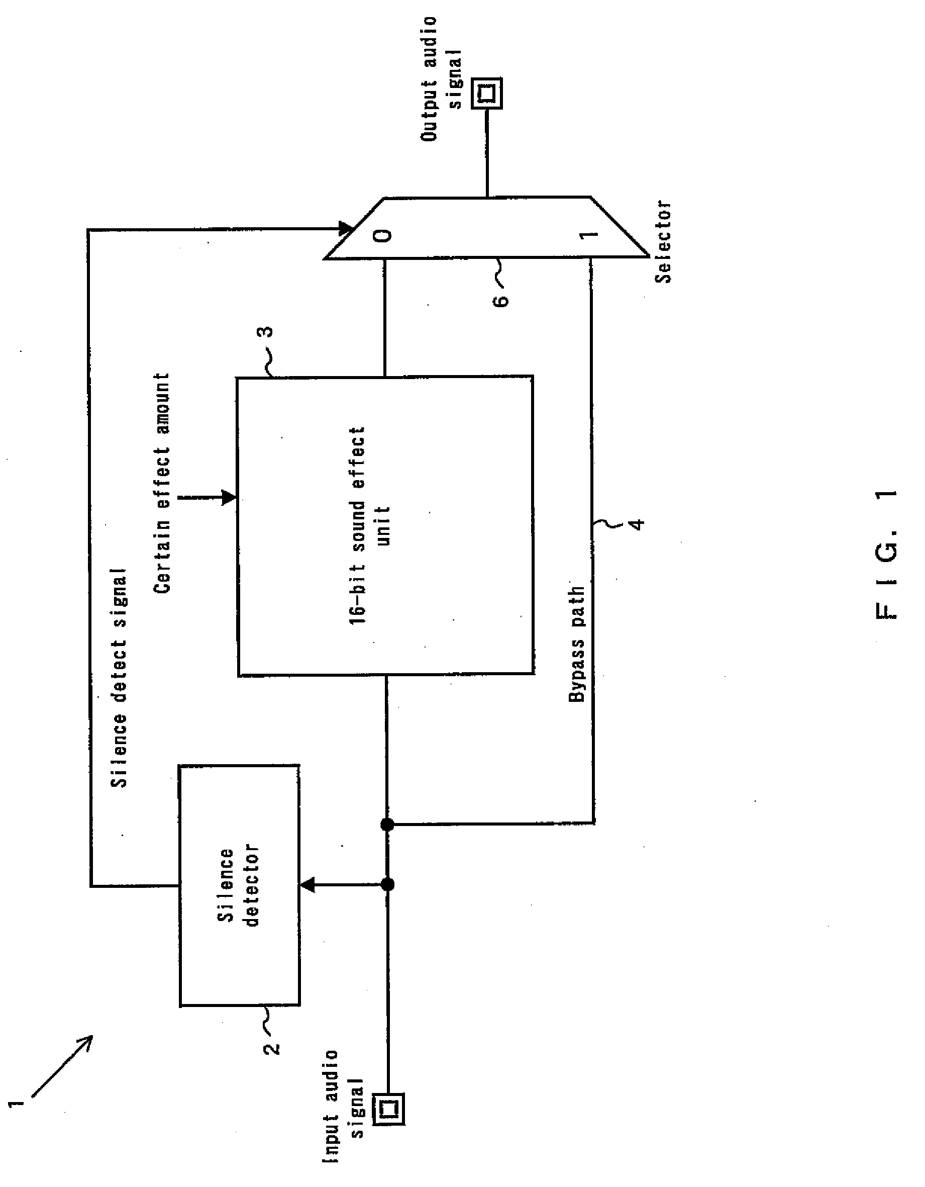
[0018]FIG. 1 shows the configuration of a sound effect circuit according to a first embodiment of the present invention. The sound effect circuit, denoted by reference numeral 1, includes a silence detector 2, a 16-bit sound effect unit 3, and a bypass path 4. The sound effect circuit 1 may be implemented as a single circuit device or a part of a semiconductor integrated circuit in which it is integrated with a digital signal processor (DSP) for performing an audio codec process and other devices.

[0019]The 16-bit sound effect unit 3 is a digital sound effect unit which is a constituent element of the present invention, and functions to provide a specific sound effect to a 16-bit quantized PCM-format input audio signal through a digital operation and output the resulting signal as a 16-bit quantized PCM-format output audio signal. The specific sound effect of the 16-bit sound effect unit 3 may be considered as, for example, enhancing or attenuating a specific low-frequency band, mid-...

second embodiment

[0027]FIG. 4 shows the configuration of a sound effect circuit according to a second embodiment of the present invention. The sound effect circuit, denoted by reference numeral 1, includes a silence detector 2, a 16-bit sound effect unit 3, and a sound effect amount controller 7. The silence detector 2 and 16-bit sound effect unit 3 have the same functions as those in the first embodiment. However, the silence detector 2 supplies a silence detect signal to the sound effect amount controller 7. Also, the 16-bit sound effect unit 3 increases or reduces its effect amount in response to a sound effect control signal supplied from the sound effect amount controller 7.

[0028]The sound effect amount controller 7 varies the level of the sound effect control signal in response to the silence detect signal to control an effect amount of a sound effect that the 16-bit sound effect unit 3 provides to an input audio signal. In detail, when the current state of the input audio signal is changed fr...

third embodiment

[0037]FIG. 6 shows the configuration of a sound effect circuit according to a third embodiment of the present invention. The sound effect circuit, denoted by reference numeral 1, includes a sound effect amount controller 7, a 16-bit sound effect unit 3, an auto level controller (ALC) 14, a programmable gain amplifier (PGA) 15, and an over-gain determiner 16. The 16-bit sound effect unit 3 and sound effect amount controller 7 have the same functions as those in the second embodiment.

[0038]The auto level controller 14 functions to output an input audio signal directly as an output audio signal. The auto level controller 14 also functions to generate a gain control signal based on the signal level of the input audio signal and supply it to the programmable gain amplifier 15, so as to maintain the volume level range of the audio signal to be constant. The programmable gain amplifier 15 varies an amplification factor thereof in response to the gain control signal supplied from the auto l...


PUM


Abstract

A sound effect circuit and processing method are disclosed. An input audio signal is input to a digital sound effect unit, an output signal is generated and output with a sound effect in accordance with an effect amount of a certain value from the input audio signal using the digital sound effect unit, the input audio signal is also input to a silence state detection unit, a silence detect signal is generated and output when detecting that the current state of the input audio signal is a silence state using the silence state detection unit, the output signal is input to a sound effect amount control unit, and an output audio signal is output using the sound effect amount control unit, wherein the sound effect amount control unit changes the effect amount to be smaller than the certain value when the silence detect signal is generated.

Description

BACKGROUND OF THE INVENTION[0001]1. Field of the Invention[0002]The present invention relates to a sound effect circuit and processing method for providing sound effects to a digital audio signal using a pulse code modulation (PCM) scheme or the like[0003]2. Description of the Related Art[0004]A sound effect circuit that provides various sound effects to a digital audio signal is well known to those skilled in the art. In this sound effect circuit, for example, a feedback circuit such as an infinite impulse response (IIR) filter may be used as a band pass filter which divides an input sound into a high-pitched tone, middle-pitched tone and low-pitched tone. However, in this feedback circuit, there is a problem that some limit cycle oscillation noise significantly occur when the level of an input audio signal is close to a silence state. As a means for settling this problem may be considered a method that internally converts the number of quantized bits of an input audio signal, for ...

Claims


Application Information

Patent Timeline
IPC IPC(8): H03G3/00
CPCH03G3/3089H04S1/007H03G5/005H03G3/341
Inventor SHIMAZAKI, KOUYASAITO, NAOTAKA
Owner LAPIS SEMICON CO LTD
Why Eureka
Try Eureka