Exhaust gas control apparatus

a technology of exhaust gas and control apparatus, which is applied in the direction of mechanical apparatus, engine components, machines/engines, etc., can solve the problems of significant loss of exhaust gas energy and loss of part of exhaust gas energy, and achieve the effect of simple, reliable and effective sealing

Inactive Publication Date: 2009-07-09
RENAULT TRUCKS
View PDF15 Cites 14 Cited by
  • Summary
  • Abstract
  • Description
  • Claims
  • Application Information

AI Technical Summary

Benefits of technology

[0017]It can also be envisaged that the apparatus includes a sealing device positioned between two adjacent inlet ports except between the two adjacent inlet ports opposite the output port as in effect each of the two sealing device which are adjacent to the output port can seal half the internal volume of the exhaust manifold.
[0018]In a further embodiment, the apparatus includes at least one valve pivotally articulated relative to the exhaust manifold and being capable of sealing one of the two adjacent inlet ports. In this embodiment, a pivotal valve provides simple, reliable and effective sealing means which channel the exhaust gas.

Problems solved by technology

Although a turbocharger can greatly increase the engine power with only a slight increase in weight, it appears that a significant part of the exhaust gas energy is lost.
Therefore, a part of the energy contained in the exhaust gas is lost as only a fraction of the kinetic and thermal energy contained in the exhaust gas arrives at the turbine.

Method used


Image

  • Exhaust gas control apparatus
  • Exhaust gas control apparatus
  • Exhaust gas control apparatus

Examples


Embodiment Construction

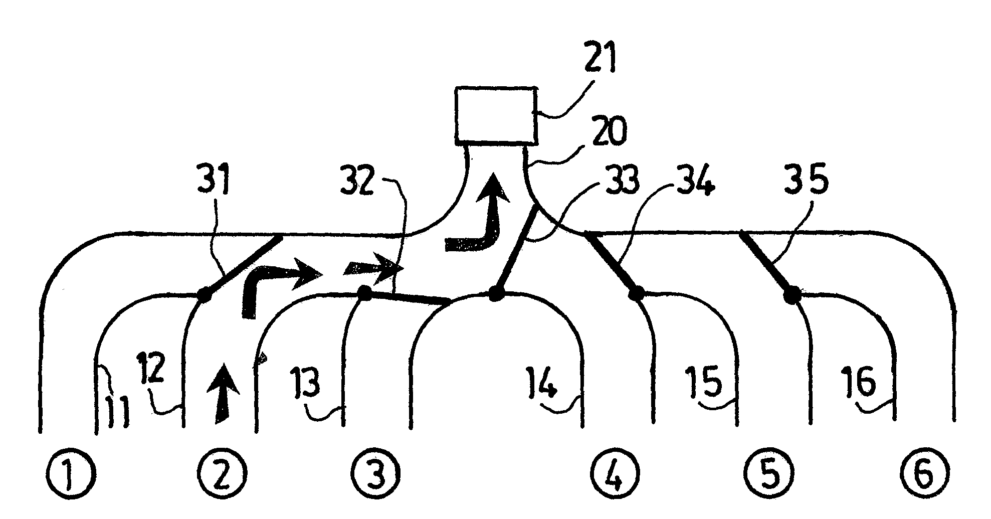
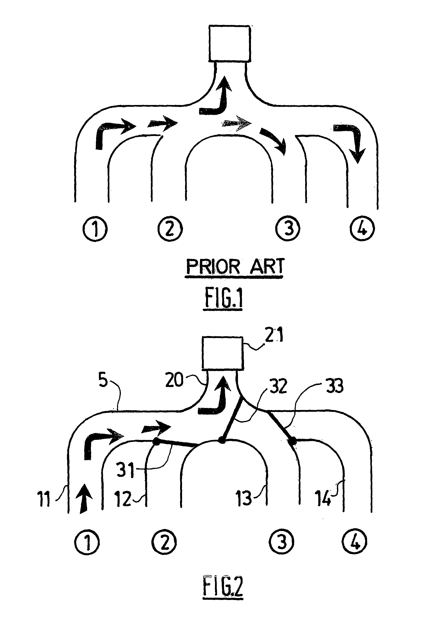
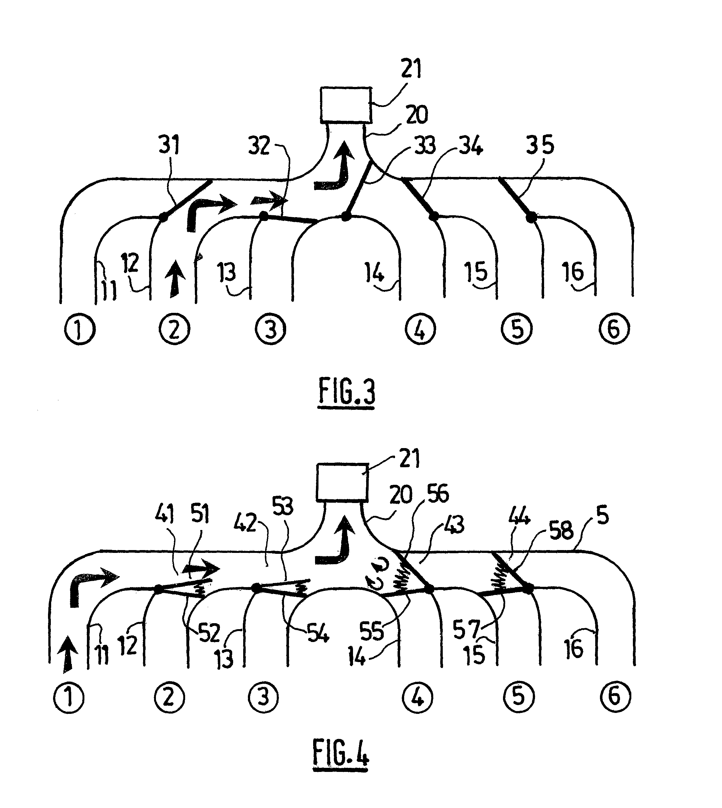
[0028]The exhaust gases control apparatus of the present invention is shown in FIGS. 2 to 6.

[0029]FIG. 2 shows an exhaust manifold 5 for a four cylinder combustion engine equipped with a first embodiment of the apparatus. The exhaust manifold 5 includes four inlet ports 11, 12, 13, 14. Each of the inlet ports 11, 12, 13, 14 is connected to one or more exhaust valves disposed in an engine cylinder head; the exhaust valve(s) release(s) the exhaust gas during the engine exhaust stroke. Neither the engine nor the exhaust valve is further described as they are not part of the present invention. The cylinders are conventionally numbered from 1 to 4.

[0030]The inlet ports 11, 12, 13, 14 merge into an output port 20 upon which a turbine 21 of a turbocharger is fixed. Although not illustrated, the turbine 21 is mechanically linked to a compressor in a known per se manner.

[0031]As depicted in FIG. 2, three valves 31, 32, 33 are disposed in the exhaust manifold. Each valve is pivotally articula...


PUM


Abstract

An exhaust gas control apparatus is provided for an internal combustion engine having at least two cylinders, a turbine, and an exhaust manifold collecting a flow of exhaust gases formed in each cylinder towards the turbine. The exhaust manifold has an inlet port connected to each cylinder and an output port upon which the turbine is secured. The exhaust gas control apparatus includes at least one seal positioned between two adjacent inlet ports, each seal being articulated relative to the exhaust manifold and being capable of sealing one of the two adjacent inlet ports to reduce the internal volume of the exhaust manifold available for the flow of exhaust gas. The apparatus of the invention makes it possible to reduce the internal volume of the exhaust manifold according to the engine cycle. By doing so, most of the kinetic energy of the exhaust gases is channelled towards the turbine; this is in contrast with a traditional exhaust manifold whereby a part of the kinetic and thermal energy of the exhaust gases is dissipated within the internal volume of all the inlet ports of the exhaust manifold.

Description

BACKGROUND AND SUMMARY[0001]The present invention relates to an exhaust gas control apparatus.[0002]Generally, a combustion engine creates work by burning a fuel such as for example gasoline, diesel or liquid petroleum gas within the engine. A combustion engine works by burning said fuel in a chamber defined by a cylinder and a moving piston which is linked to a crankshaft.[0003]To increase its power output, a combustion engine can be equipped with a turbocharger. A turbocharger is an exhaust driven compressor which increases the mass of oxygen entering the engine. Conventionally, a turbocharger includes a gas compressor in the intake tract of the engine which compresses the intake air above the atmospheric pressure. The compressor is driven by a turbine which uses waste energy from the exhaust gas. To this end, the compressor and the turbine are connected to a unique shaft.[0004]Although a turbocharger can greatly increase the engine power with only a slight increase in weight, it ...

Claims


Application Information

Patent Timeline
Patent Type & Authority Applications(United States)
IPC IPC(8): F01N5/04F01N13/10
CPCF01N13/10F01N2240/20F01N2290/10Y02T10/144F02B37/02F02B37/22F02B37/004Y02T10/12
Inventor LORTET, DIMITRILEJEUNE, MARC
Owner RENAULT TRUCKS
Why Eureka
Try Eureka