Pressure support ventilation of patients

a technology for ventilators and patients, applied in the direction of valve operating means/release devices, catheters, diagnostic recording/measuring, etc., can solve the problems of loss of ventilatory support, loss of supplemental oxygen, loss of end expiratory splinting pressure, etc., and achieve only very partially effective control of mouth leakag

Inactive Publication Date: 2009-07-09
RESMED LTD
View PDF21 Cites 47 Cited by
  • Summary
  • Abstract
  • Description
  • Claims
  • Application Information

AI Technical Summary

Problems solved by technology

However, there are some untoward effects of ventilatory support on the patient as follows:
A mouth leak of 0.4 L / sec causes severe sleep disruption, loss of ventilatory support, loss of supplemental oxygen, and loss of end expiratory splinting pressure.
A chin strap is only very partially effective in controlling mouth leak.
Unlike passive pharyngeal collapse, it is not known whether vocal cord closure responds to CPAP, but if it is an active closure it would be expected to be extremely refractory to CPAP.
However, it can cause considerable discomfort, by various mechanisms:Distension of upper airway structures.Swallowing of air (particularly once pressures exceed 20 cmH2O)Mask discomfort.Leak, particularly mouth leak.Patient-machine asynchrony.
However, discomfort from all the causes bulleted above will increase.
Leaks, and particularly variable leaks, cause asynchrony because the airflow measured by the device does not equal the patient respiratory airflow.
At 0.6 L / sec, the device will probably not really be benefiting the patient.
Keeping the leak much below 0.2 L / sec is technically very demanding and not generally practicable.
Patient-machine asynchrony is particularly a problem in patients with long respiratory time constants being treated with high degrees of support.
This is because even true respiratory airflow no longer equals patient effort.
The higher the degree of support results in greater difficulty with the phenomenon.
Intrinsic PEEP causes a kind of asynchrony because the patient must generate a considerable inspiratory effort before any flow is generated.
Absent a uniform methodology for adjusting the settings of such a device, the delivery of the appropriate degree of pressure support to the patient may not be optimal.

Method used


Image

  • Pressure support ventilation of patients
  • Pressure support ventilation of patients
  • Pressure support ventilation of patients

Examples


Embodiment Construction

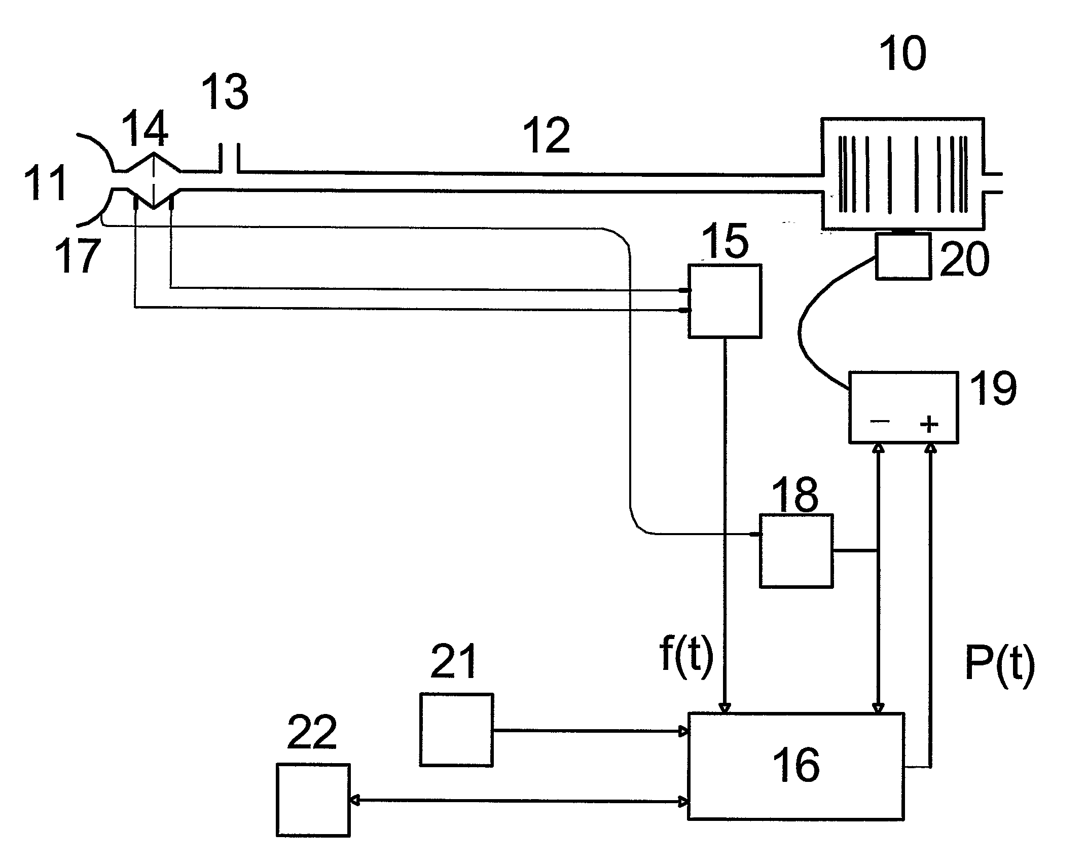
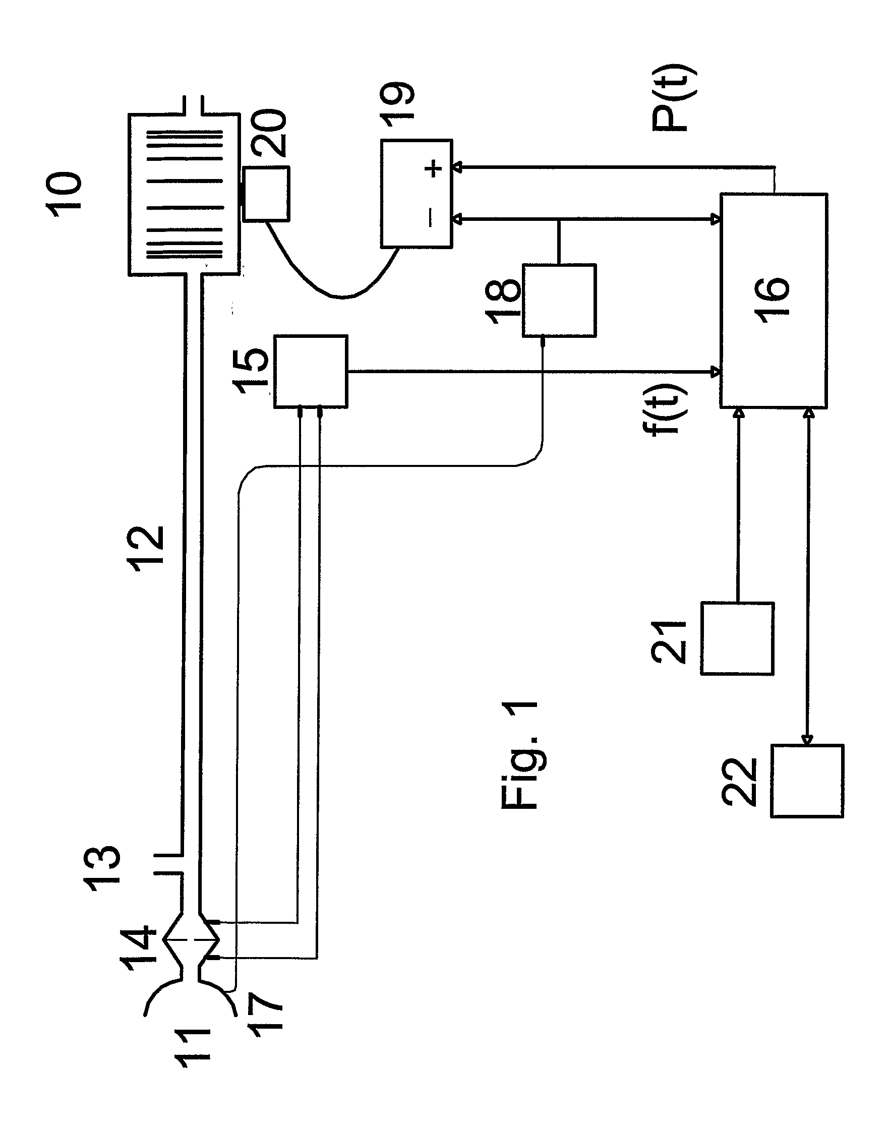
[0070]A servo-controlled ventilator useful for accomplishing the invention is shown in FIG. 1. A blower 10 supplies air under pressure via delivery tube 12 to a mask 11 or via another such device for providing flow to a patient's respiratory system. Exhaust gas is vented via exhaust 13. Mask flow is preferably measured using pneumotachograph 14 and differential pressure transducer 15 to derive flow signal f(t). Mask pressure is measured at pressure tap 17 using pressure transducer 18. Flow and pressure signals are sent to a controller or microprocessor 16 including a memory which implements the processing described herein to derive a pressure request signal P(t). Programmed instructions accessible to the microprocessor are coded on integrated chips in the memory of the device or may be loaded as software and stored by some other data storage medium of conventional design (not shown). The actual measured pressure and pressure request signal P(t) are fed to motor servo 19 which contro...


PUM


Abstract

A methodology and apparatus for determining ventilator settings including an end expiratory pressure setting, pressure swing, resistive unloading and target ventilation for delivering ventilatory support based upon generalized patient ventilation characteristics and / or disease classifications. An apparatus may be programmed with the instructions to accomplish the methodology interactively by prompting the user / physician during setup and calculating settings based upon measurements or input responses. Pre-assigned values associated with ventilation characteristics or disease classifications may be combined with a base pressure value or measured values to provide patient customized settings or adjustments to determine pressure levels for the delivery of ventilatory support.

Description

[0001]This application claims the priority filing date of U.S. provisional patent application Ser. No. 60 / 306,972 filed on Jul. 19, 2001.FIELD OF THE INVENTION[0002]This invention relates to methods and devices for providing ventilatory assistance to a patient. More specifically, the invention involves an improved method and device for adjusting the device settings to provide ventilation to satisfy a patient's respiratory needs.BACKGROUND OF THE INVENTION[0003]In untreated patients with lung, chest wall, or control abnormalities, blood gases typically deteriorate somewhat in NREM sleep, and then deteriorate much further in REM sleep. This deterioration is likely due to multiple causes, including:[0004]1. Increased upper airway resistance due to pharyngeal collapse.[0005]2. Loss of cough and sigh, leading to sputum retention and atelectasis.[0006]3. Postural effects on V / Q.[0007]4. Reduced tonic or chemoreflex drive to the diaphragm, particularly in REM.[0008]5. Reduced tonic or chem...

Claims


Application Information

Patent Timeline
Patent Type & Authority Applications(United States)
IPC IPC(8): A61M16/00
CPCA61M16/00A61M2016/0021A61M2016/0036A61M16/0069A61M16/0057A61M16/06A61M2230/202A61M16/024
Inventor BERTHON-JONES, MICHAEL
Owner RESMED LTD
Why Eureka
Try Eureka