
Multifunctional output drivers and multifunctional transmitters using the same

a multi-functional, output driver technology, applied in pulse generators, pulse techniques, baseband system details, etc., can solve the problems of constant power consumption and differential low-voltage signaling of cml circuits

Inactive Publication Date: 2009-07-09
MEDIATEK INC
View PDF5 Cites 28 Cited by
  • Summary
  • Abstract
  • Description
  • Claims
  • Application Information

AI Technical Summary

Benefits of technology

[0007]Because different display panels require different transmission interfaces, there is a need for a multifunctional output driver capable of transmitting signals of different interfaces in different modes in order to reduce costs and power consumption.

Problems solved by technology

CML circuits use differential low-voltage signaling and have constant power consumption.

Method used


Image

  • Multifunctional output drivers and multifunctional transmitters using the same
  • Multifunctional output drivers and multifunctional transmitters using the same
  • Multifunctional output drivers and multifunctional transmitters using the same

Examples


Embodiment Construction

[0019]The following description is of the best-contemplated mode of carrying out the invention. This description is made for the purpose of illustrating the general principles of the invention and should not be taken in a limiting sense. The scope of the invention is best determined by reference to the appended claims.

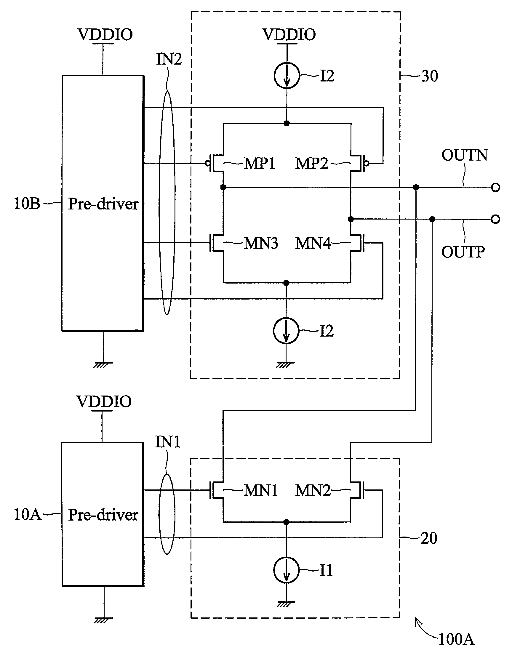
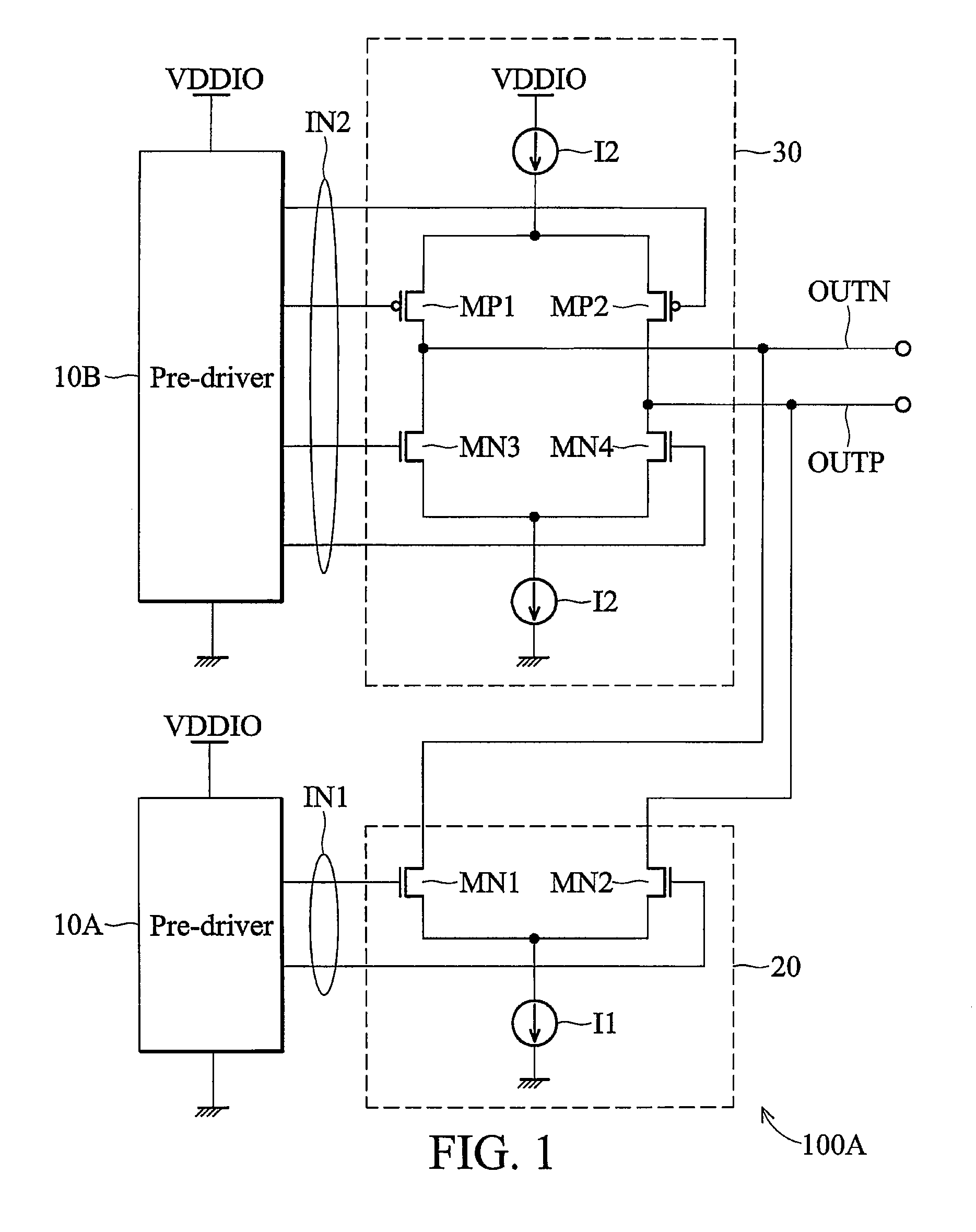
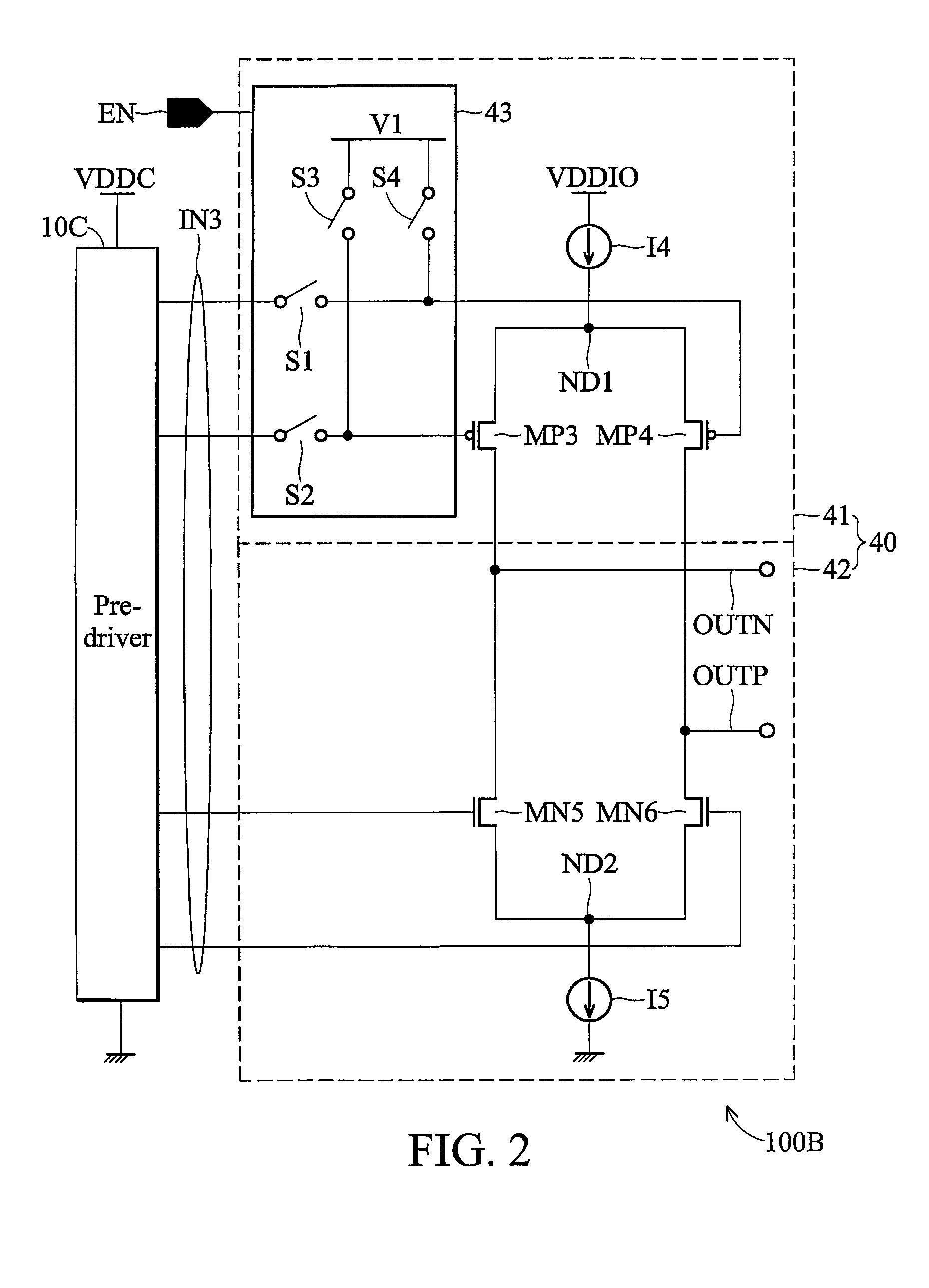
[0020]FIG. 1 is a schematic diagram of an embodiment of a multifunctional transmitter. As shown, a multifunction transmitter 100A comprises two pre-drivers 10A and 10B and two output drivers 20 and 30 for outputting signals compatible with a first transmission interface in a first transmission mode and signals compatible with a second transmission interface in a second transmission mode. The first transmission interface and the second transmission interface can, for example, be a low voltage differential signaling (LVDS) transmission interface and a current mode logic (CML) transmission interface, respectively, but is not limited thereto. The pre-drivers 10A and 10B an...


PUM


Abstract

A multifunctional output driver capable of transmitting signals of different interfaces in different modes is provided, in which first and second current sources are provided, and first to fourth switching devices are coupled between the first and second current sources, and the first and second current source and the first to the fourth switching devices act as a current steering circuit. In a first transmission mode, the first and second switching devices are turned off, and the third and fourth switching devices and the first current source act as a current mode logic circuit to provide an output signal compatible with a first transmission interface according to an input signal from a pre-driver. In a second transmission mode, the current steering circuit outputs an output signal compatible with a second transmission interface according to the input signal from the pre-driver.

Description

CROSS REFERENCE TO RELATED APPLICATIONS[0001]This application claims the benefit of U.S. Provisional Application No. 61 / 018,680, filed Jan. 3, 2008, the entirety of which is incorporated by reference herein.BACKGROUND OF THE INVENTION[0002]1. Field of the Invention[0003]The invention relates to output drivers, and more particularly, to multifunctional output drivers capable of transmitting signals of different specifications in different modes.[0004]2. Description of the Related Art[0005]Low voltage differential signaling, or LVDS, is an electrical signaling system that can run at very high speeds over twisted-pair copper cables. LVDS is a differential signaling system, which means that it transmits two different voltages which are compared at the receiver. LVDS uses the difference in voltage between the two wires to encode information. The transmitter injects a small current, nominally 3.5 mA, into one wire or the other, depending on the logic level to be sent. The current passes t...

Claims


Application Information

Patent Timeline
Patent Type & Authority Applications(United States)
IPC IPC(8): H03K3/00
CPCH03K19/018528H04L25/028H04L25/0272
Inventor LUO, YAN-BINCHEN, TUN-SHIHCHOU, MIN-CHUNG
Owner MEDIATEK INC
Learn More