
Start-Up Control Device and Start-Up Control Method for Internal Combustion Engine

a technology of start-up control device and internal combustion engine, which is applied in the direction of electric control, combustion air/fuel air treatment, instruments, etc., can solve the problems of high-pressure fuel pump, fuel may leakage, and fuel may leakage from the injector

Inactive Publication Date: 2009-07-09
TOYOTA JIDOSHA KK
View PDF7 Cites 9 Cited by
  • Summary
  • Abstract
  • Description
  • Claims
  • Application Information

AI Technical Summary

Benefits of technology

[0015]The present invention has been made in view of the foregoing problem, and provides a start-up control device and method for an internal combustion engine that can adequately avoid start-up failure without unnecessarily actuating a fuel pump.
[0021]According to the above start-up control device and method for an internal combustion engine, a plurality of regions are defined by the fuel temperature and the fuel pressure in consideration of the saturation fuel vapor pressure of the fuel. The regions include, for example, a region at high temperature and high pressure, a region at low temperature (low pressure), and an intermediate region provided therebetween. It is presumed that fuel vapor is generated based on the relationship with the saturation fuel vapor pressure of the fuel in the high-temperature high-pressure region and the intermediate region, of the three regions. In the high-temperature high-pressure region, there is a still residual pressure, as suggested by the expression “high-pressure,” even if fuel vapor is generated. Thus, the fuel pressure can increase immediately and excellent startability can be achieved without preliminary driving the fuel pump before starting up the internal combustion engine (hereinafter referred to as “pre-feeding”), even if the fuel pump is started at the same time as a start-up request. In this way, it is not necessary to pre-feed in the high-temperature high-pressure region, even if fuel vapor is generated. On the other hand, in the low-temperature (low-pressure) region, fuel vapor is not generated. Thus, the fuel pressure can increase immediately and excellent startability can be achieved without pre-feeding, even if the fuel pump is started at the same time as a start-up request. In this way, it is not necessary to pre-feed in the low-temperature (low-pressure region), because no fuel vapor is generated. In the intermediate region, however, fuel vapor is generated and there is not a sufficient residual pressure. Thus, if the fuel pump is started at the same time as a start-up request without pre-feeding, it would take a long time for the fuel pressure to increase and excellent startability could not be achieved. In this way, it is necessary to pre-feed only in the intermediate region. To sum up, it is presumed that fuel vapor is generated when the detected fuel temperature and fuel pressure are determined to fall into the intermediate region of the plurality of regions defined by the relationship between the fuel temperature and the fuel pressure and the saturation fuel vapor pressure characteristics of the fuel, and pre-feeding is performed before cranking only when the fuel vapor affects the startability of the internal combustion engine. This allows for pre-feeding only when fuel vapor that affects the startability of the internal combustion engine is generated. As a result, it is possible to provide a start-up control device for an internal combustion engine that can adequately avoid start-up failure without unnecessarily actuating the fuel pump.

Problems solved by technology

When any type of engine including either or both of a in-cylinder injector and an intake passage injector is stopped, left alone and then restarted, a problem as described below occurs.
However, fuel may leak due to a seal failure, or fuel may leak from the injector if a foreign matter is caught in a fuel injection nozzle of the injector.
High-pressure fuel pumps inevitably have a clearance with its pump plunger.
This also causes the decrease in the fuel pressure from the engine stop, which causes the fuel to boil under a reduced pressure and thus be vaporized in the piping.
Such fuel vapor generated in the fuel piping prevents the pressure in the fuel piping from immediately increasing to a feed pressure, thus adversely affecting the startability of the engine.
If the fuel pump is operated in this way, the operating life of the fuel pump is shortened, and the so-called “NV” (Noise and Vibration) problem is caused by operation of the fuel pump before engine start-up.

Method used


Image

  • Start-Up Control Device and Start-Up Control Method for Internal Combustion Engine
  • Start-Up Control Device and Start-Up Control Method for Internal Combustion Engine
  • Start-Up Control Device and Start-Up Control Method for Internal Combustion Engine

Examples


Embodiment Construction

[0041]In the following description and the accompanying drawings, the present invention will be described in more detail with reference to exemplary embodiments. In the following description, identical components are given identical reference numerals. They are also given identical names and functions. Thus, the detailed description will not be repeated for the components.

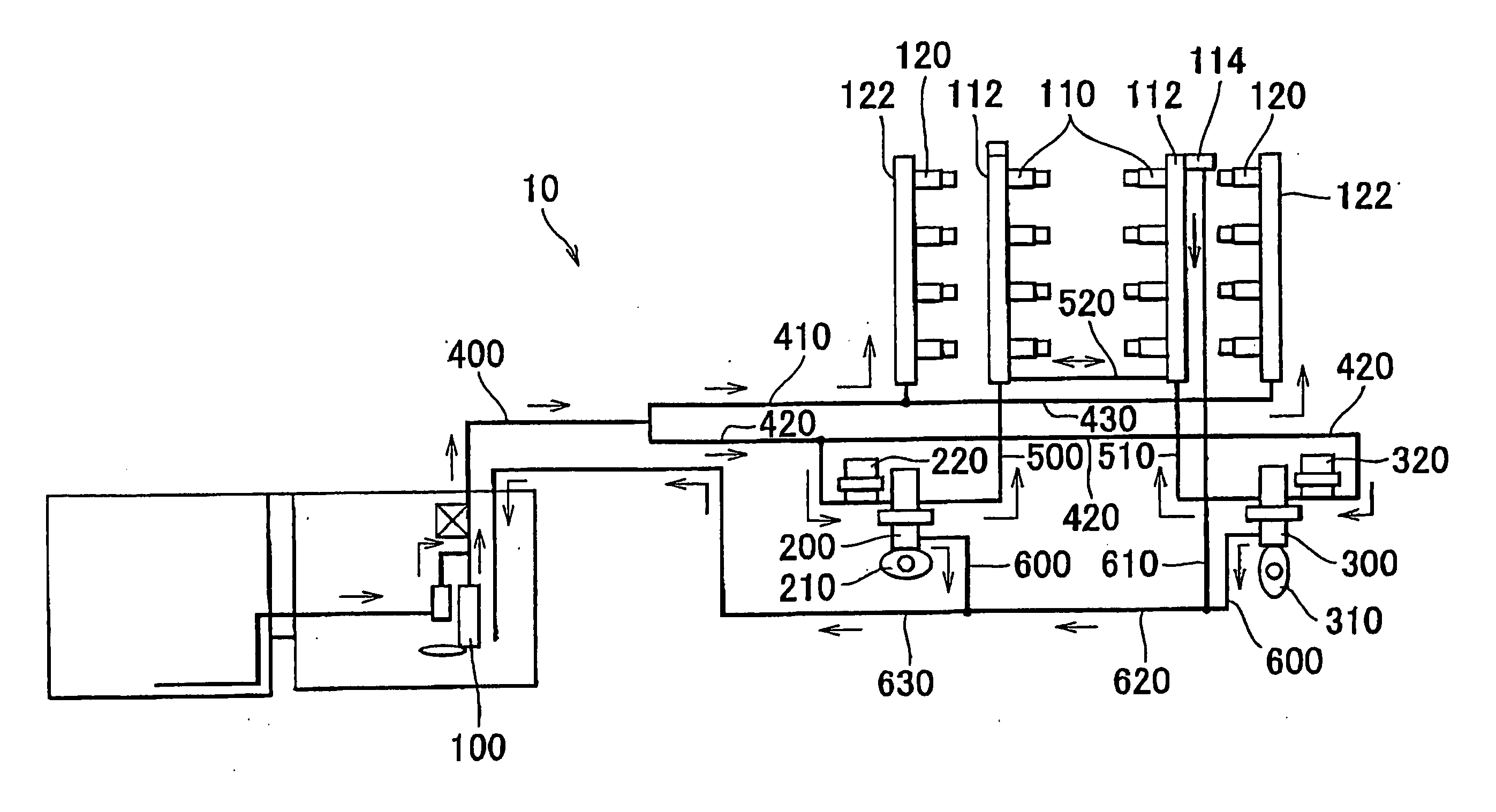
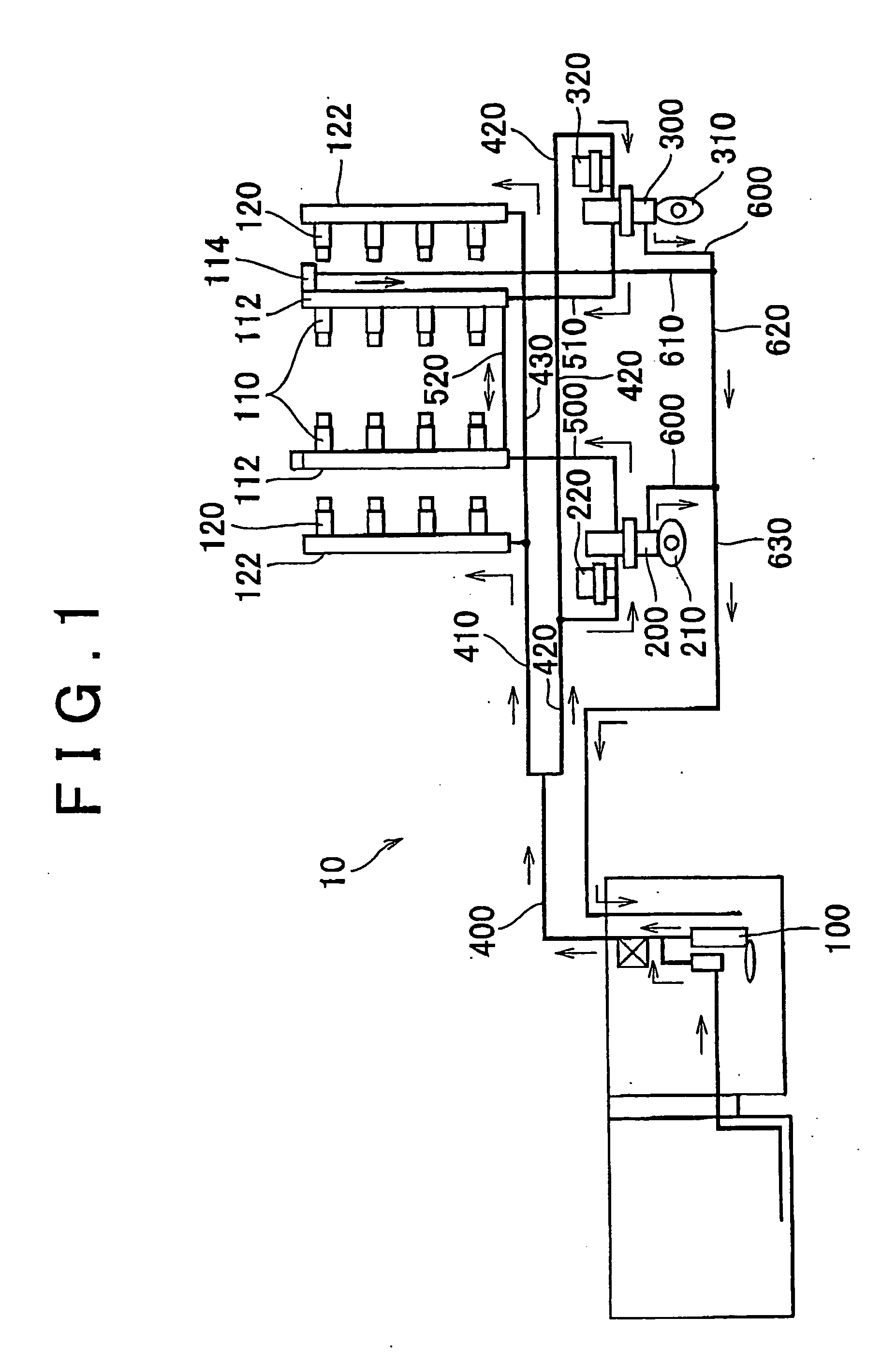
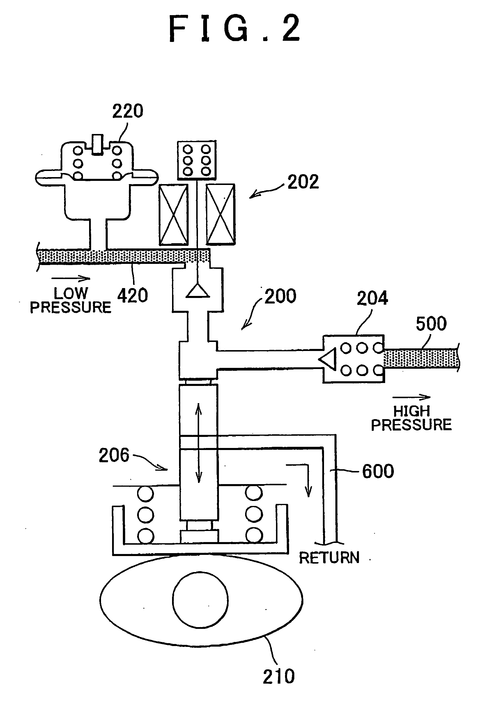
[0042]FIG. 1 shows a fuel supply system 10 including a start-up control device according to an embodiment of the present invention. This engine is a V8 gasoline engine having in-cylinder injectors 110 for injecting fuel into respective cylinders and intake passage injectors 120 for injecting fuel into respective intake passages for the cylinders. The present invention may be applied not only to this type of engine, but also to other types of gasoline engines and common rail diesel engines. The engine may have more or less than two high-pressure fuel pumps.

[0043]The engine may have only either intake passage injecto...


PUM


Abstract

An engine ECU stores a map in which a region at high temperature and high pressure, a region at low temperature and low pressure, and a region provided therebetween are defined by the relationship between the temperature and pressure of fuel and the saturation fuel vapor pressure of the fuel. The engine ECU executes a program including the following steps: when start-up of the engine is requested, detecting the engine cooling water temperature and the fuel pressure; if the detection results fall into the region, setting a pre-feed time; pre-feeding until the fuel pressure reaches a desired fuel pressure threshold; and when the fuel pressure reaches the fuel pressure threshold, starting cranking. In this way, start-up failure due to fuel vapor can be avoided without unnecessarily actuating a fuel pump.

Description

BACKGROUND OF THE INVENTION[0001]1. Field of the Invention[0002]The present invention relates to a start-up control device and method for an internal combustion engine having either or both of a fuel injection mechanism for injecting fuel into a cylinder at high pressure (in-cylinder injector) and a fuel injection mechanism for injecting fuel into an intake port (intake passage injector), and more particularly to a technique to actuate a fuel pump before cranking.[0003]2. Description of the Related Art[0004]A gasoline engine is known that includes a first fuel injection valve for injecting fuel into a combustion chamber (in-cylinder injector) and a second fuel injection valve for injecting fuel into an intake passage (intake passage injector) and that adjusts the distribution of fuel between the in-cylinder injector and the intake passage injector according to the engine speed or the engine load. A direct-injection gasoline engine that includes only a fuel injection valve for inject...

Claims


Application Information

Patent Timeline
IPC IPC(8): F02D41/06F02M7/00F02D45/00F02M37/08F02N19/00
CPCF02D41/401F02D2200/0602F02D2200/0606F02D41/3836F02N19/00F02D41/003F02D41/062F02M59/366F02D41/3094
Inventor AKITA, TATSUHIKOSAKAI, MITSUTOKURATA, NAOKI
Owner TOYOTA JIDOSHA KK
Learn More