Internal combustion engine driven turbo-generator for hybrid vehicles and power generation

Inactive Publication Date: 2009-07-16
INTERNAL COMBUSTION TURBINES
View PDF2 Cites 64 Cited by
  • Summary
  • Abstract
  • Description
  • Claims
  • Application Information

AI Technical Summary

Benefits of technology

[0015]The embodiments disclosed herein provide the desirable effect of combining the efficiency of a linear piston engine and turbine driven electrical generator as an integrated operating system for inc

Problems solved by technology

In a standard engine the forces applied by the expanding gas in the combustion chamber are converted to a force on the connecting rod that is not parallel to the cylinder axis for the majority of its motion resulting in substantial side forces and friction.
However, there are still a few challenges which plague free piston engines including preventing the piston from hitting the cylinder head, controlling valves for inlet and exhaust, and converting the linear piston motion to a power output.
Consequently, such low speed generators are significantly more expensive.
In addition the electronics required for conversion of low frequency AC output from an electrical generator e

Method used


Image

  • Internal combustion engine driven turbo-generator for hybrid vehicles and power generation
  • Internal combustion engine driven turbo-generator for hybrid vehicles and power generation
  • Internal combustion engine driven turbo-generator for hybrid vehicles and power generation

Examples


first embodiment

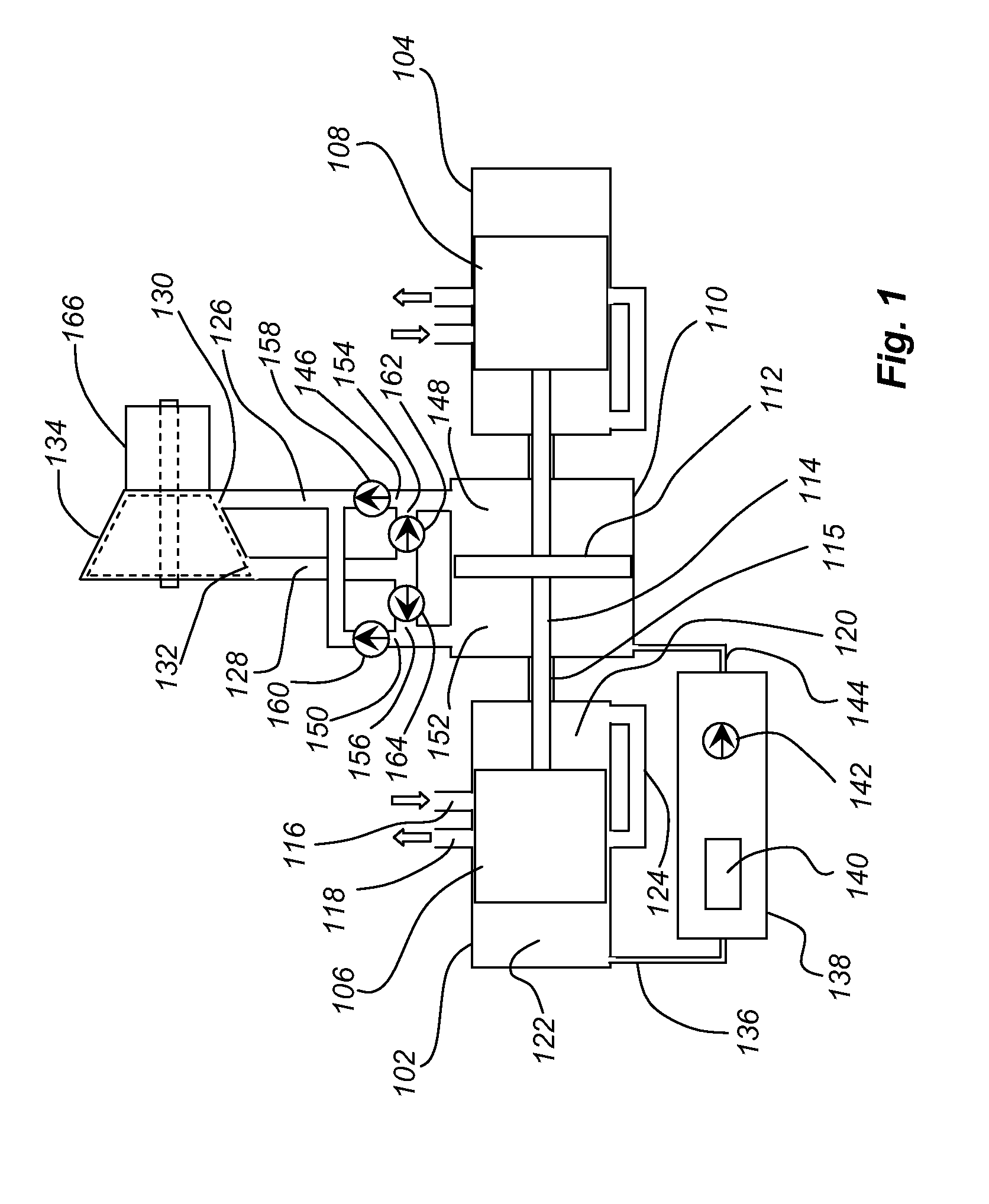
[0030]Referring to the drawings, a detailed schematic of the present invention is shown in FIG. 1. Two linearly opposed combustion cylinders 102 and 104 house drive pistons 106 and 108 respectively to provide an internal combustion section for the engine. A displacement cylinder 110 resides intermediate the combustion cylinders and houses a displacement piston 112. Connecting rod 114 interconnects the first and second drive pistons with the displacement piston for reciprocating motion. In alternative embodiments the connecting rod may be configured as two separate rods interconnecting the first and second drive pistons with the displacement piston. Conduits 115 provide passage for the connecting rod between pressurization sumps 120 and displacement cylinders.

[0031]For the two-stroke combustion cycle embodiment shown in FIG. 1, each combustion cylinder incorporates an inlet port 116 and an outlet port 118. A pressurization sump 120 for the inlet charge is connected to combustion cham...

second embodiment

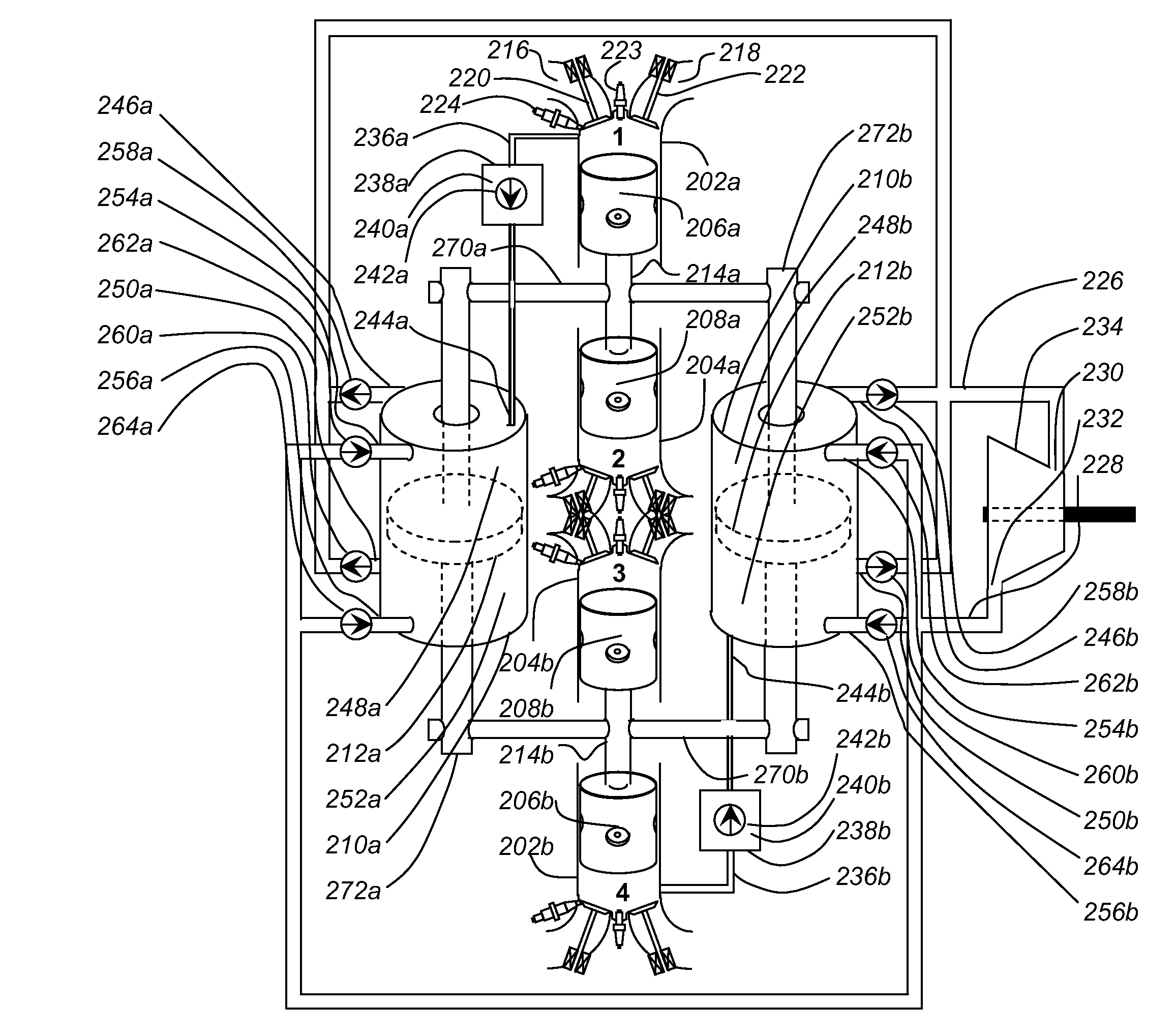
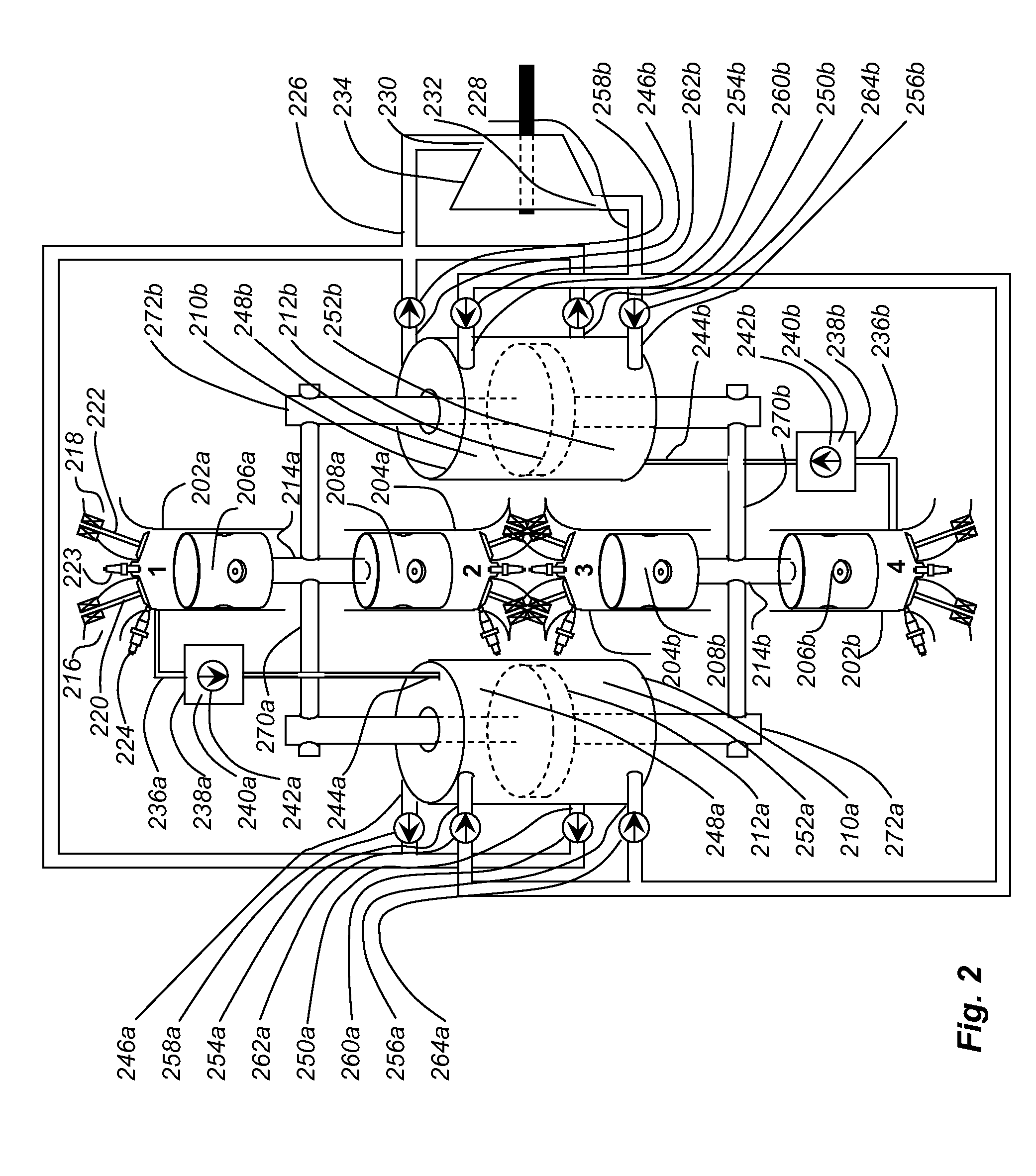
[0037]In certain applications a four-stroke combustion cycle may be desirable. FIG. 2 shows the invention which employs a four-stroke cycle with two cylinder and piston pairs coupled with two displacement cylinders. Two linearly opposed combustion cylinders 202a and 204a are employed to house drive pistons 206a and 208a respectively. Similarly, two linearly opposed combustion cylinders 202b and 204b are employed to house drive pistons 206b and 208b respectively. The pairs of cylinders are axially aligned for the embodiment shown in the drawings. Two displacement cylinders 210a and 210b reside symmetrically adjacent and axially parallel to the combustion cylinders and each houses a displacement piston 212a and 212b respectively. Connecting rods 214a and 214b linearly interconnect the first and second drive pistons in each set with the displacement pistons driven by lateral rods 270a and 270b perpendicularly extending from the connecting rods and driving parallel rods 272a and 272b in...

third embodiment

[0040]FIG. 3 schematically demonstrates a third embodiment employing a two-stroke cycle wherein the volumes associated with the combustion cylinders as pressurization sumps in the embodiment of FIG. 1 act as the working gas displacement compartments for the engine. The faces of the drive piston opposite the combustion surface in the combustion chamber provide the function of the displacing surfaces of the displacement piston in the embodiment of FIG. 1. A first cylinder 302 and a second cylinder 304 house a first piston 306 and a second piston 308. A connecting rod 310 interconnects the two pistons. Each piston has a combustion surface 316 exposed to the combustion chamber 318. A displacing working surface 320 on a face of each piston opposite the combustion surface operates in a displacement compartment 322. For the configuration shown in FIG. 3 the displacement compartments are interconnected by a channel 312 for passage of the connecting rod with appropriate sealing gaskets 314 t...


PUM


Abstract

A piston compression system converts energy from a conventional combustion cycle engine driving a piston to displace a working gas for flow through a turbine for output power. The working gas is derived by diverting a portion of the charge during combustion at near peak combustion pressure (PCP) into a closed working volume. The working gas is maintained at high pressure within the working volume. The working volume has a first displacement compartment and a second displacement compartment, a supply manifold connected for receiving pressurized working gas alternately from the first and second compartments and connected to an inlet of the turbine, and a return manifold connected to an outlet of the turbine and alternately returning working gas to the second and first compartments. The engine is configured with first and second pistons housed in first and second combustion cylinders respectively powering a first displacing surface for displacement of working gas in the first compartment and a second displacing surface for displacement of working gas in the second compartment.

Description

REFERENCE TO RELATED APPLICATIONS[0001]This application claims priority of U.S. Provisional applications Ser. No. 61 / 066,037 filed on Feb. 15, 2008 entitled Internal Combustion Turbine, Ser. No. 61 / 010,989 filed on Jan. 14, 2008 entitled Gas-bearings Generators and Ser. No. 61 / 065,080 filed on Feb. 9, 2008 entitled Crankless Engine, all having a common inventor with the present application, the disclosure of each provisional being fully incorporated herein by reference as though fully set forth.BACKGROUND[0002]1. Field[0003]This invention relates generally to the field of internal combustion engines for electrical power generation and more particularly to a linear piston internal combustion engine providing displacement of a working gas for driving a low pressure ratio turbine.[0004]2. Description of the Related Art[0005]Piston driven internal combustion engines typically require conversion of linear motion of one or more pistons to rotational motion of a crankshaft through the use ...

Claims


Application Information

Patent Timeline
IPC IPC(8): H02K7/18F04B35/00B60L50/15
CPCB60K6/24B60K6/26B60K6/46B60Y2400/435Y02T10/6217Y02T10/6295F02B71/04Y02T10/62
Inventor YARON, RAN
Owner INTERNAL COMBUSTION TURBINES
Why Eureka
Try Eureka