The relatively high levels of CO2 in the earth's oceans are believed to increase the acidity levels of the ocean's water, which in turn adversely effects
marine life.
However,
nuclear power plants are viewed with scorn by many people in society as they are the source of nuclear waste which presents difficult choices in terms of determining suitable locations for disposal.
However, hydroelectric power plants are extremely expensive to construct and
pose their own problems to the environment.
Also, the minimum operational
wind speed (
cut-in speed) of HAWTs is relatively high and the maximum
wind speed (
cut-out speed) that can be endured is relatively low, allowing for only a relatively narrow window of operation, beyond which they are prone to damage and have to stop operating.
Furthermore, the serviceable components of HAWTs usually sit high up in the so-called
nacelle, on top of a tall pillar, which is rather inconvenient for servicing and replacement of parts.
Moreover, although HAWTs are considered “fast-runners” based on their lift factor, the actual slewing speed of HAWTs is relatively low (typically in the range of 15 to 30 RPM), which necessitates expensive multi-stage gearboxes and negatively impacts the overall
system efficiency and costs.
Further, the overall design of HAWTs does not facilitate or make practical “do-it-yourself construction.”
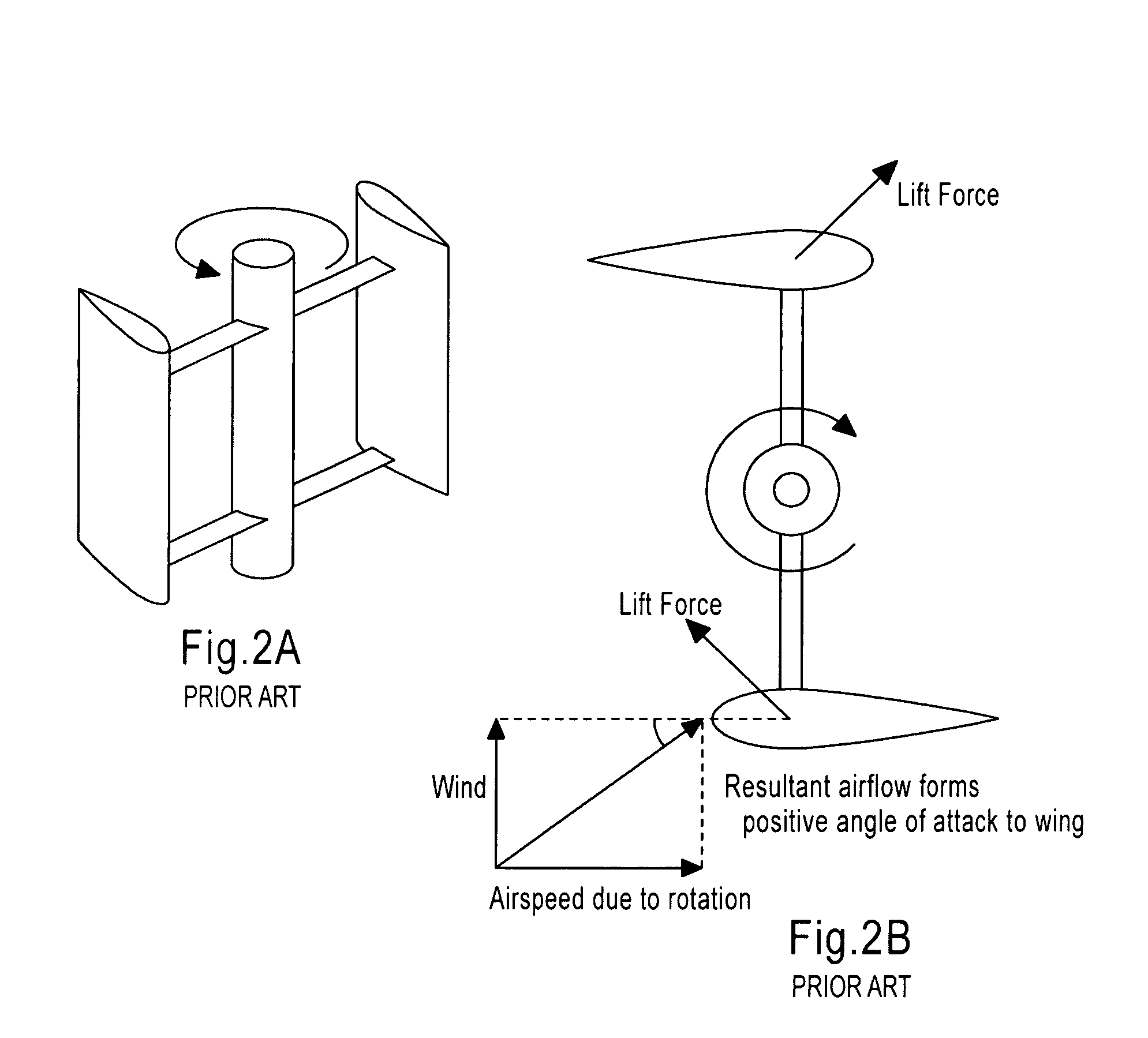
The aeronautical terms lift and drag are, strictly speaking, forces across and along the approaching sail relative to the
airflow, so they are not useful here.
One problem with the design is that the
angle of attack changes as the turbine
spins, so each sail generates its
maximum torque at two points on its cycle (front and back of the turbine).
This leads to a sinusoidal (pulsing)
power cycle that complicates the overall design.
Another problem with the design arises due to the
mass of the rotating mechanisms being at the periphery rather than at the hub, as with a
propeller.
Additionally, guy wires are not easily used to offset the load because the
propeller spins both above and below the top of the
tower.
Overall, while there are some advantages in the aforementioned Darrieus design, there are many more disadvantages, especially with bigger machines in the MW class.
Also, the Darrieus design uses more expensive materials for the sails while most of the sail is too close to the ground to provide enough power.
So far, there is no known material (including carbon
fiber) which can meet cyclic load requirements of the Darrieus design.
While in theory the Darrieus design is as efficient as the
propeller type design if the
wind speed is constant, in practice such efficiency is rarely realized due to the physical stresses and limitations imposed by the practical design and wind speed variations.
There are also substantial difficulties in protecting the Darrieus turbine from extreme wind conditions and in making it a self-starting assembly.
One drawback to this design is that the sail pitching mechanism is complex and generally heavy, and a wind-direction sensor must be added to the design in order to properly
pitch the sails.
While rather low in efficiency but high in torque, the Savonius turbine is used mainly for
weed grinding and
water pumping applications.
The structure of this design requires a complex adjusting mechanism, wherein the reaction time to any such adjustment is rather slow due to the size of the sails.
The sails of this design, which are rather large, are also prone to damage because of their latency to react to the changing wind directions.
However, the flap size of the big flap design limits the operation of the turbines and the design does not lend itself to large turbines.
Drag type VAWTs have a substantially low efficiency, which is determined by the ratio between the latent wind energy and the actual
power output.
One of the main reasons for the inefficiency is half of the sail is moving in the
wrong direction, that is, towards the oncoming wind, at any given time.

