Cryosurgical System

a cryosurgical and system technology, applied in the field of cryosurgical systems, can solve the problems of excessive use of cryogen, inefficient heat transfer, cryoprobes utilizing joule-thomson systems, etc., and achieve the effects of less nitrogen, less radiation, and sufficient cooling power

Inactive Publication Date: 2009-07-16
SANARUS TECHNOLOGIES
View PDF9 Cites 8 Cited by
  • Summary
  • Abstract
  • Description
  • Claims
  • Application Information

AI Technical Summary

Benefits of technology

[0011]The devices and methods described below provide for use of liquid nitrogen in cryoablation systems while minimizing the amount of cryogen used during cryosurgical procedures. The system uses cryoprobes of coaxial structure, and is supplied with cryogen from a dewar of liquid nitrogen. The system includes various enhancements to avoid heat transfer from the liquid nitrogen to the system components, and as a result permits use of very low-pressure nitrogen, and, vice-versa, the use of low pressure nitrogen permits use of the various enhancements (which could not be used in a high pressure system). The result is a system that provides sufficient cooling power to effectively ablate lesions, tumors and masses within the breast of female patients while using very little nitrogen and a compact and inexpensive system based on readily available and easy to handle liquid nitrogen.

Problems solved by technology

Present cryoprobes utilizing Joule-Thomson systems have inherent disadvantages such as inefficient heat transfer and excessive use of cryogen.
As a result, these systems require large quantities of gasses under high pressure and high flow rates.
Use of high-pressure gasses increases the overall costs of cryoprobes.
This is due to the high cost of materials required for use with systems utilizing high-pressure gases, the high costs associated with obtained high pressure gases and the large quantities of cryogen required for use with these systems.
The literature and patent filings indicate that liquid nitrogen systems were plagued by various problems, such as vapor lock and excessive consumption of liquid nitrogen.
Systems like those disclosed in Rubinsky '181, Rubinski '218 and Littrup are complicated and expensive to manufacture.
However, in actual practice as liquid nitrogen boils, a thin layer of nitrogen gas inevitably forms on the inner surface of the closed probe tip end.
Other inefficiencies found in traditional cryoprobe systems include vapor lock.
Vapor lock occurs when the back pressures produced by the boiling LN2 reduce the LN2 flow into the freezing zone, thereby further reducing the efficiency of the probe tip cool.
The high pressure required in Littrup necessitate the use of expensive materials and fittings to maintain the cryogen at these pressures and prevent system failure.
Additionally, because the liquid nitrogen is lightly pressurized, the boiling point remains low, and the liquid temperature also remains low compared with higher pressure systems.

Method used


Image

  • Cryosurgical System
  • Cryosurgical System
  • Cryosurgical System

Examples


Embodiment Construction

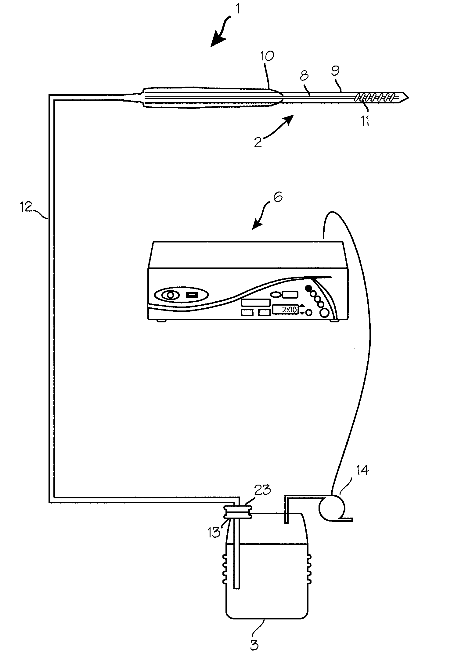
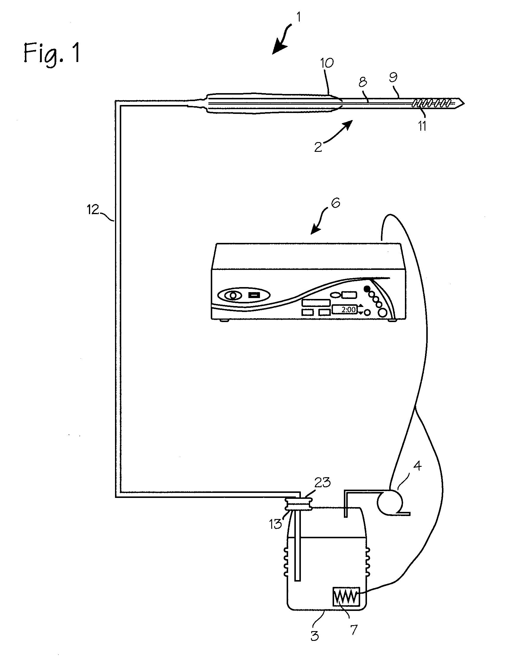
[0023]FIG. 1 illustrates a cryosurgical system which uses liquid nitrogen as a cryogen. The cryosurgical system 1 comprises cryoprobe 2, a cryogen source 3, pressurization pump 4, and a control system 6 for controlling the control valve. The system may also be provided with a cryogen source heater 7 placed in thermal communication with the cryogen source. The desired flow of cryogen from the dewar to the cryoprobe is induced in this embodiment by pressurizing the cryogen source with air delivered by the pressurized pump. The cryosurgical system 1 may be adapted to accommodate multiple cryoprobes with the addition of appropriate manifolds, and the control system may be computer-based or otherwise operable to automatically control the pressure and flow rate and other system components to effect the cooling profiles for desired cryosurgeries.

[0024]The cryogenic system 1 is arranged without a control valve in fluid communication with the fluid pathway. The necessary cryogen flow rate of...


PUM


Abstract

A cryosurgical system using a low-pressure liquid nitrogen supply, which requires only 0.5 to 15 bar of pressure to provide adequate cooling power for treatment of typical breast lesions. The pressure may be provided by supplying lightly pressurized air into the dewar, by heating a small portion of the nitrogen in the dewar, or with a small low pressure pump.

Description

[0001]This application is a continuation application of 11 / 406,547, filed Apr. 18, 2006.FIELD OF THE INVENTIONS[0002]The inventions described below relate the field of cryosurgical systems.BACKGROUND OF THE INVENTIONS[0003]Cryosurgery refers to the freezing of body tissue in order to destroy diseased tissue. Minimally invasive cryosurgical systems generally include a long, slender cryoprobe adapted for insertion into the body so that the tip resides in the diseased tissue, and source of cryogenic fluid, and the necessary tubing to conduct the cryogenic fluid into and out of the probe. These cryosurgical systems also include heating systems, so that the probes can be warmed to enhance the destructive effect of the cryoablation and to provide for quick release of the cryoprobes when ablation is complete.[0004]Our own Visica® cryoablation system has proven effective for the treatment of lesions within the breast of female patients. The system uses Joule-Thompson cryoprobes, and uses ar...

Claims


Application Information

Patent Timeline
Patent Type & Authority Applications(United States)
IPC IPC(8): A61B18/02
CPCA61B18/02A61B2018/0268A61B2018/00041
Inventor DELONZOR, RUSSELL L.ROSS, JAMES B.NALIPINSKI, MATHEW J.TURNER, KEITHFOSTER, DAVID J.CANE, MICHAEL R.RICHARDS, SAMUEL C.SELVEY, DAVID J.
Owner SANARUS TECHNOLOGIES
Why Eureka
Try Eureka