Inertial sensor

a sensor and inertial technology, applied in the direction of acceleration measurement using interia forces, turn-sensitive devices, instruments, etc., can solve the problems of large damping effect due to air, inability to vibrate the vibrating body in a state with high frequency and large amplitude, and greatly affected the fine vibrating body formed by micromachining techniques, etc., to improve the detection sensitivity of angular rate sensors, suppress displacement sensitive, and improve the detection sensitivity of acceleration sensors

Active Publication Date: 2009-07-23
HITACHI LTD
View PDF6 Cites 24 Cited by
  • Summary
  • Abstract
  • Description
  • Claims
  • Application Information

AI Technical Summary

Benefits of technology

[0010]Hence, the inertial sensor having the angular rate sensor and the acceleration sensor is conceivable to take a configuration as shown in Patent Document 1. That is, the vibrating body for the angular rate sensor and the movable body for the acceleration sensor are disposed on the same substrate, whereas the vibrating body for the angular rate sensor and the movable body for the acceleration sensor are disposed in the space portions respectively in different atmospheric pressures. Specifically, the vibrating body for the angular rate sensor is disposed in the space portion airtightly sealed in a low pressure state, and the movable body for the acceleration sensor is disposed in the space portion airtightly sealed in a high pressure state. With such a configuration, the vibrating body for the angular rate sensor can vibrate in high frequency and large amplitude without being affected by the damping due to air, thereby improving the detection sensitivity of the angular rate sensor. On the other hand, since the movable body for the acceleration sensor is placed under a high pressure, it receives an effect of the damping due to air, and can suppress the displacement sensitive more than necessary, and as a result, the detection sensitivity of the acceleration sensor can be improved. Consequently, according to the inertial senso

Problems solved by technology

However, a fine vibrating body formed by a micromachining technique is greatly affected by damping of the air.
Since the damping is a force generated proportional to the speed of the vibrating body, under a high pressure, when an attempt is made to vibrate the vibrating body in a state where the speed is fast, that

Method used


Image

  • Inertial sensor
  • Inertial sensor
  • Inertial sensor

Examples


first embodiment

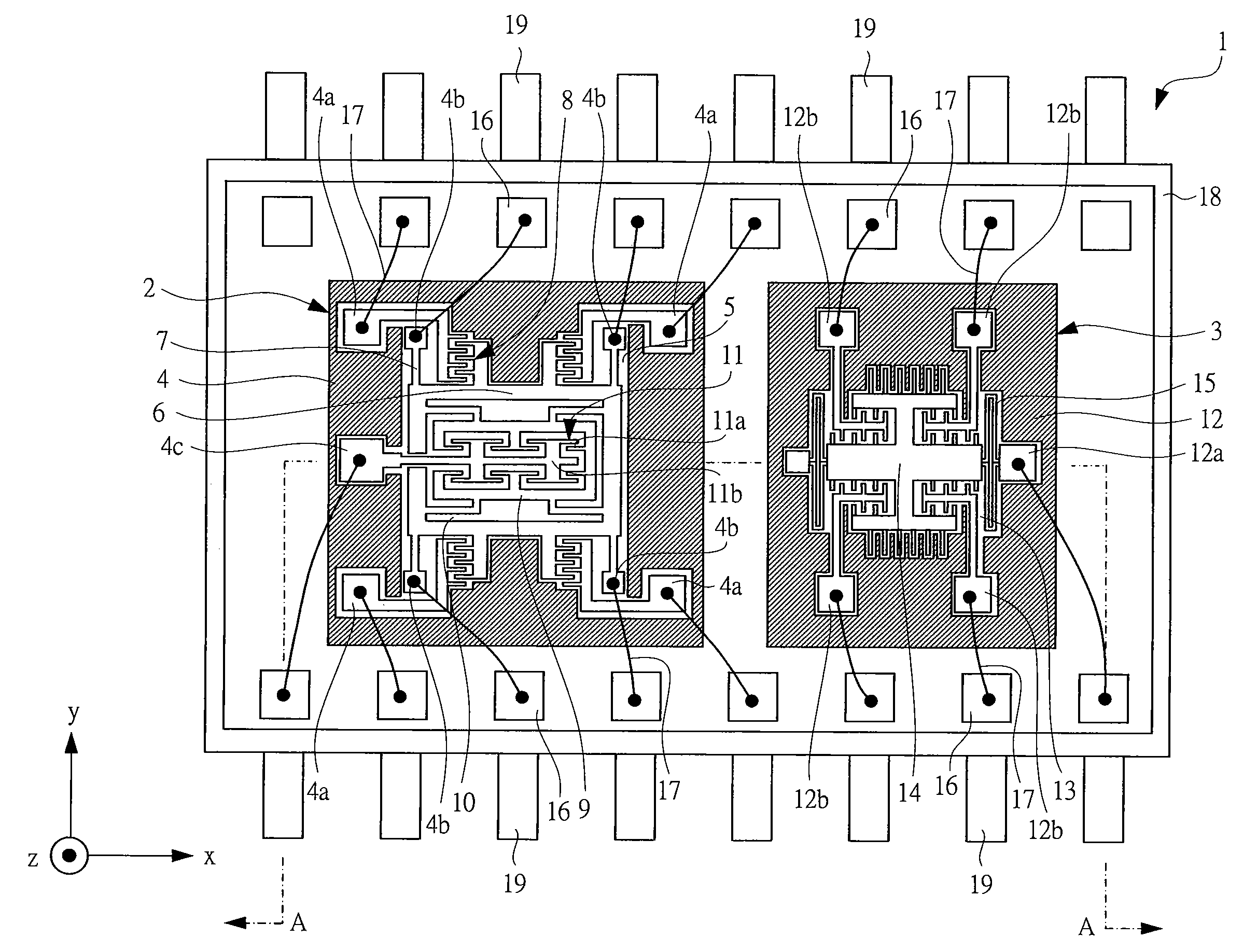
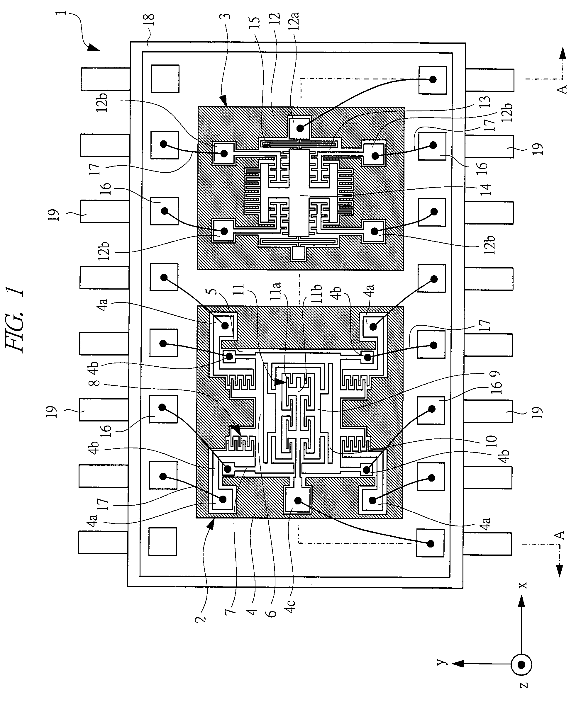
[0036]An inertial sensor in a first embodiment will be described with reference to the drawings. FIG. 1 is a plan view showing an inertial sensor according to the first embodiment. In FIG. 1, an inertial sensor 1 includes an angular rate sensor 2 and an acceleration sensor 3. In FIG. 1, the angular rate sensor 2 and the acceleration sensor 3 are formed in separate semiconductor chips.

[0037]First, a configuration of the angular rate sensor 2 will be described. As shown in FIG. 1, the angular rate sensor 2 has a cavity portion (first cavity portion) 5 formed in the interior of a rectangular periphery portion (first periphery portion) 4. In the interior of this cavity portion 5, a fixing portion 4a, a fixing portion (first fixing portion) 4b, a fixing portion 4c, and a vibrating body 6 are formed. The vibrating body 6 is connected to the fixing portion 4b by an elastic deforming portion (first elastic deforming portion; support beam) 7. Further, between this vibrating body 6 and the fi...

second embodiment

[0077]While descriptions have been made on the example in which the angular rate sensor and the acceleration sensor are formed in separate semiconductor substrates (semiconductor chips) in the first embodiment, in the second embodiment, descriptions will be made on an example in which the angular rate sensor and the acceleration sensor are formed in the same semiconductor substrate (semiconductor chip).

[0078]FIG. 5 is a plan view showing an inertial sensor 1 in the second embodiment. As shown in FIG. 5, the packaging method of the inertial sensor 1, the internal gas pressure, the configuration and the effect of the shift suppressing portion (damper) 23 are the same as the already described case where the acceleration sensor and the angular rate sensor are formed on the separate semiconductor substrates. A difference lies in the point that the angular rate sensor and the acceleration sensor are formed on the same semiconductor substrate. That is, since the angular rate sensor and the...

third embodiment

[0082]For example, in an inertial sensor in which an acceleration sensor and an angular rate sensor are integrated on the same semiconductor substrate (one chip), the acceleration sensor and the angular rate sensor can be disposed inside a space of the same kind and having the same pressure. Hence, the inertial sensor can be managed easily by a wafer level package (WLP) as shown in FIG. 7. While the angular rate sensor and the acceleration sensor are formed in the individual chip areas formed in the semiconductor wafer, before singulating the chip area formed with the angular rate sensor and the acceleration sensor, a technique for sealing each chip area by a cap is referred to as a wafer level package. FIG. 7 is a schematic cross-sectional view showing a configuration of the inertial sensor subjected to wafer level packaging, and showing a state in which the angular rate sensor and the acceleration sensor formed on the same semiconductor substrate 25a are sealed by a cap 27, and th...


PUM


Abstract

An angular rate sensor and an acceleration sensor are sealed at the same sealing pressure. The sealing pressure at this time is put into a reduced pressure state below the atmospheric pressure in view of improving a detection sensitivity of the angular rate sensor. Even in the reduced pressure atmosphere, to improve the detection sensitivity of the acceleration sensor, a shift suppressing portion (damper) for suppressing shifts of a movable body of the acceleration sensor is provided. This shift suppressing portion includes a plurality of protruding portions integrally formed with the movable body and a plurality of protruding portions integrally formed with a peripheral portion, and the protruding portions are alternately disposed separately at equal intervals.

Description

CROSS-REFERENCE TO RELATED APPLICATION[0001]The present application claims priority from Japanese Patent Application No. JP 2008-010388 filed on Jan. 21, 2008, the content of which is hereby incorporated by reference into this application.TECHNICAL FIELD OF THE INVENTION[0002]The present invention relates to an inertial sensor, particularly, it relates to a technique effectively applied to an inertial sensor provided with an angular rate sensor and an acceleration sensor.BACKGROUND OF THE INVENTION[0003]Japanese Patent Application Laid-Open Publication No. 2002-005950 (Patent Document 1) discloses a technique that aims to improve detection sensitivity by both of an angular rate sensor and an acceleration sensor. Specifically, a planar vibrating body of the angular rate sensor and a movable body of the acceleration sensor are disposed on the same substrate in a floating state interposing a space between them. Then, a lid member is formed above the planar vibrating body and the movabl...

Claims


Application Information

Patent Timeline
IPC IPC(8): G01P15/08G01C19/56G01C19/5762G01C19/5769G01P15/125H01L29/84
CPCG01C19/5719G01P1/02G01P15/0802B81B2201/0242B81B7/02B81B2201/0235G01P15/125
Inventor YAMANAKA, KIYOKOTAKANO, HIDEAKI
Owner HITACHI LTD
Why Eureka
Try Eureka