Electrically Powered Vehicle

Inactive Publication Date: 2009-07-23
TOYOTA JIDOSHA KK
View PDF7 Cites 85 Cited by
  • Summary
  • Abstract
  • Description
  • Claims
  • Application Information

AI Technical Summary

Benefits of technology

[0019]In the present invention, the inverter device operates either in the first operation mode (running mode) in which the rotating electric machine is driven to rotate, or the second operation mode (charge/discharge mode) in which the inverter device is operated as a voltage converter for supplying and receiving electric power between the power source or power load outside the vehicle and the power storage device. In the second operation mode, the controller changes either the switching frequency or switching speed of the switching element included in the inverter device from that in the firs

Problems solved by technology

On/off operations of a switching element included in the inverter generate electromagnetic noise in the inverter.
During electric power supply and reception as such, electromagnetic noise from the inverter possibly poses a significant problem.
Further, if electric power is supplied and received between the power source or electric load outside the vehicle and t

Method used


Image

  • Electrically Powered Vehicle
  • Electrically Powered Vehicle
  • Electrically Powered Vehicle

Examples


embodiment 1

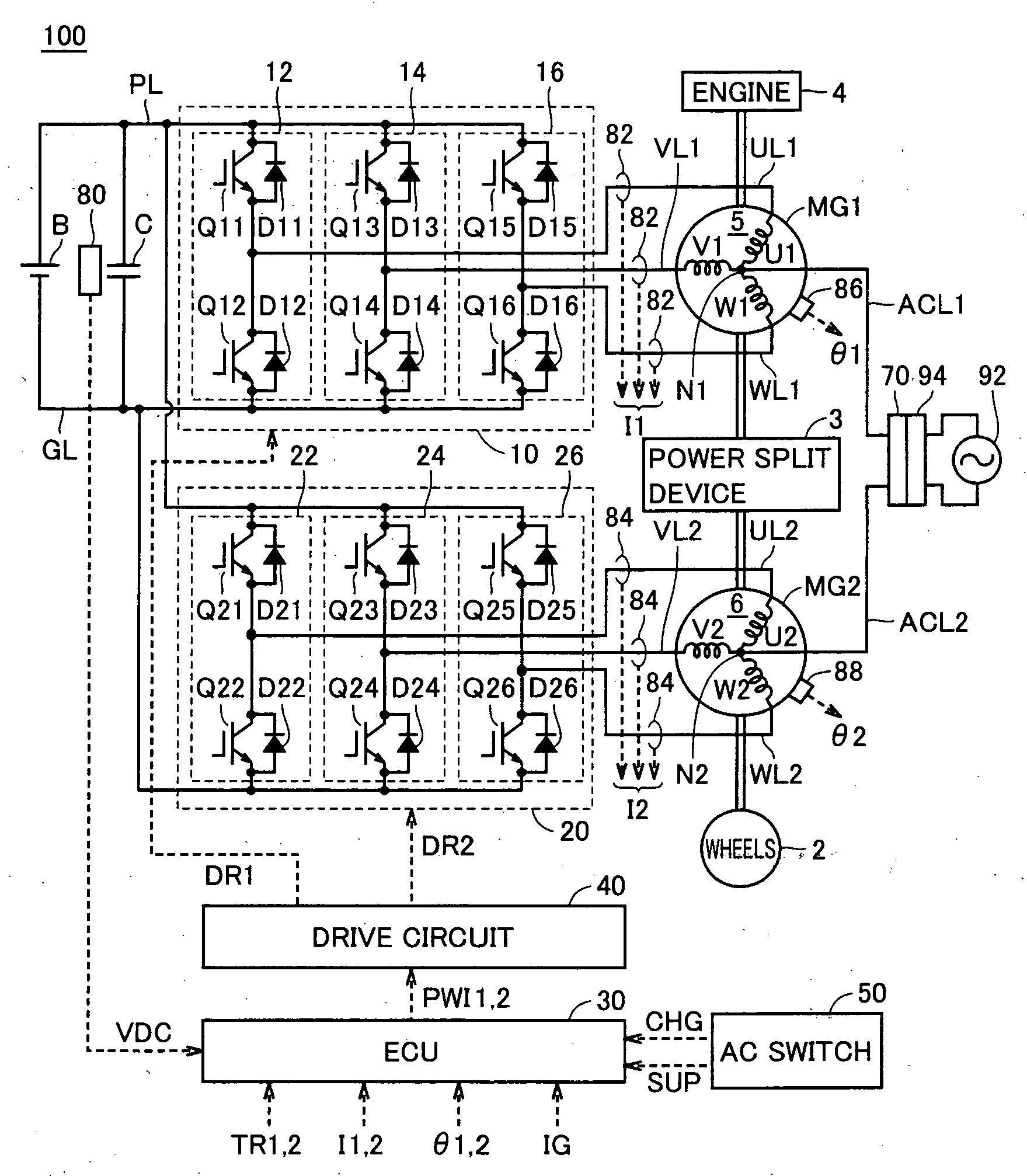
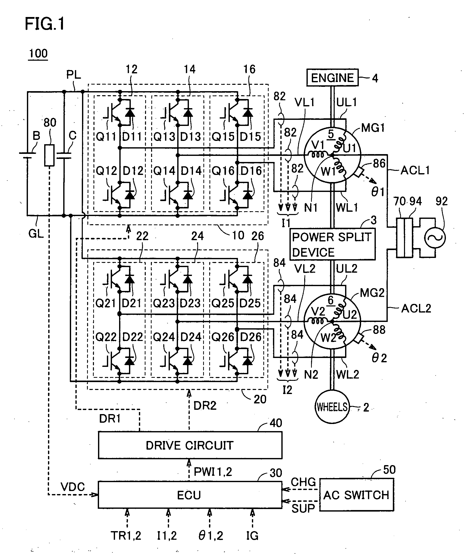
[0033]FIG. 1 is an overall block diagram of the hybrid vehicle shown as an example of the electrically powered vehicle in accordance with the present invention. Referring to FIG. 1, a hybrid vehicle 100 includes an engine 4, motor generators MG1 and MG2, a power split device 3, and wheels 2. Hybrid vehicle 100 further includes a power storage device B, inverters 10 and 20, an ECU (Electronic Control Unit) 30, a drive circuit 40 and an AC switch 50.

[0034]Hybrid vehicle 100 further includes a power line PL, a ground line GL, a capacitor C, U-phase lines UL1 and UL2, V-phase lines VL1 and VL2, W-phase lines WL1 and WL2, a voltage sensor 80, current sensors 82 and 84, and rotation angle sensors 86 and 88. Further, hybrid vehicle 100 includes power lines ACL1 and ACL2 and a connector 70.

[0035]Hybrid vehicle 100 runs using engine 4 and motor generator MG2 as power sources. Power split device 3 is coupled to engine 4 and to motor generators MG1 and MG2, and distributes power among these. B...

modification 1

of Embodiment 1

[0074]In Modification 1, the carrier frequency fc for the charge / discharge mode is set only in late night hours when the noise is particularly bothering.

[0075]FIG. 5 is a flowchart for setting the carrier frequency in accordance with Modification 1 of Embodiment 1. Referring to FIG. 5, the flowchart includes, in addition to the flowchart of FIG. 4, a step S12. Specifically, if it is determined at step S10 that the operation is in the charge / discharge mode, carrier signal generating unit 38 determines whether it is in a preset late night hours (for example, 22:00 to 6:00) or not (step S12).

[0076]If the time is determined to be in the late night hours (YES at step S12), control proceeds to step S20 at which carrier signal generating unit 38 sets the carrier frequency of each of carrier signals FC1 and FC2 to the frequency fc for the charge / discharge mode.

[0077]If it is determined at step S12 that the time is not in the late night hours (NO at step S12), control proceeds...

modification 2

of Embodiment 1

[0078]In Modification 2, noise around the vehicle is detected and the carrier frequency fc for the charge / discharge mode is set only when noise around the vehicle is low.

[0079]FIG. 6 is an overall block diagram of a hybrid vehicle in accordance with Modification 2 of Embodiment 1. Referring to FIG. 6, hybrid vehicle 100A includes, in addition to the configuration of hybrid vehicle 100 shown in FIG. 1, a noise sensor 52, and includes, in place of ECU 30, an ECU 30A.

[0080]Noise sensor 52 detects noise level around hybrid vehicle 100A, and outputs a signal DB that changes in accordance with the detected noise level, to ECU 30A.

[0081]ECU 30A determines the operation mode (running mode, charge / discharge mode) of inverters 10 and 20 based on the ignition signal IG and the charge request signal CHG and supply request signal SUP from AC switch 50, and based on the determined operation mode and the signal DB from noise sensor 52, determines carrier frequency of the carrier sig...


PUM


Abstract

In a charge/discharge mode, an inverter performs power conversion between a power storage device and a commercial power supply electrically connected to a neutral point through a power line. In the charge/discharge mode, ECU sets a carrier frequency of the inverter to a frequency higher than in a running mode. Further, in the charge/discharge mode, a drive circuit drives the inverter using a gate resistance higher than in the running mode.

Description

TECHNICAL FIELD[0001]The present invention relates to an electrically powered vehicle and, more specifically, to an electrically powered vehicle allowing electric power supply and reception between a power storage device and a power source or an electric load outside the vehicle.BACKGROUND ART[0002]Japanese Patent Laying-Open No. 4-295202 discloses a motor drive apparatus capable of supplying and receiving electric power between an AC power supply outside a vehicle and a DC power supply provided in the vehicle. The motor drive apparatus includes a battery, inverters IA and IB, induction motors MA and MB, and a control unit. Induction motors MA and MB include Y-connected windings CA and CB, respectively. To neutral points NA and NB of windings CA and CB, an input / output port is connected through an EMI filter. Inverters IA and IB are provided corresponding to induction motors MA and MB, respectively, and connected to windings CA and CB, respectively. Inverters IA and IB are connected...

Claims


Application Information

Patent Timeline
IPC IPC(8): H02J7/04H02P27/06H02J7/14B60L50/10
CPCB60K1/02Y02T90/14B60K6/445B60L9/28B60L11/005B60L11/123B60L11/14B60L11/1801B60L11/1811B60L11/1812B60L11/1814B60L11/1816B60L11/1851B60L15/007B60L2220/12B60L2220/14B60L2220/54B60L2240/423B60W10/08B60W10/26B60W20/00B60W2710/083H02P2209/01Y02T10/6217Y02T10/6239Y02T10/641Y02T10/642Y02T10/7005Y02T10/7022Y02T10/705Y02T10/7077Y02T10/7258Y02T90/127B60K6/365Y02T10/7072B60L53/14B60L53/22B60L50/53B60L50/40B60L50/61B60L50/16B60L53/20B60L53/24B60L58/10Y02T10/62Y02T10/64Y02T10/70Y02T10/72H02P27/06B60K6/26B60W20/15Y02T90/12
Inventor KUNO, HIROMICHI
Owner TOYOTA JIDOSHA KK
Why Eureka
Try Eureka