Self ballasted celestial tracking apparatus

Inactive Publication Date: 2009-07-30
SUNPOWER CORPORATION
View PDF13 Cites 57 Cited by
  • Summary
  • Abstract
  • Description
  • Claims
  • Application Information

AI Technical Summary

Benefits of technology

[0029]The invention is a celestial tracking apparatus that resists overturning forces due to wind in part through gravitational forces acting on the moving ele

Problems solved by technology

Practically speaking, mechanical considerations can limit the range of motion such that the tracking apparatus might not be able to address all arbitrary points in the sky.
However, in many applications, such as solar energy collection systems, the range of desired orientations is also limited to a subset of the visible sky.
As such, single axis tracking apparatuses, which are generally not capable of orienting the energy collection device perfectly normal to the solar radiation, are commonly used in solar PV systems.
Further, dual axis designs may not have the dynamic range required to address a large portion of the sky while maintaining the high accuracy required for high concentration PV modules or for telescope applications.
While not always the case, the wind is a substantially horizontal phenomenon, and as such tends to impart lateral loads.
Among other effects, lateral loads acting above the base of the apparatus tend to impart an overturning moment.
Primary among these is the additional cost of excavation required to insert the foundation into the ground.
Another consideration with dug-in foundations is that variability in soil conditions can make it difficult to predict how much resistance to overturning the foundation can provide without measuring soil conditions at the precise location where the foundation will be placed.
While this type of foundation reduces the cost and variability concerns associated with the dug-in foundations mentioned above by reducing the excavation costs, the amount of material required to provide sufficient mass for the foundation can result in an inefficient use of materials.
While wind resistant tracking apparatus foundation designs are both well known and effective, these designs are by no means optimal.
In particular, traditional foundation designs are costly, with the cost of materials and installati

Method used


Image

  • Self ballasted celestial tracking apparatus
  • Self ballasted celestial tracking apparatus
  • Self ballasted celestial tracking apparatus

Examples


first embodiment

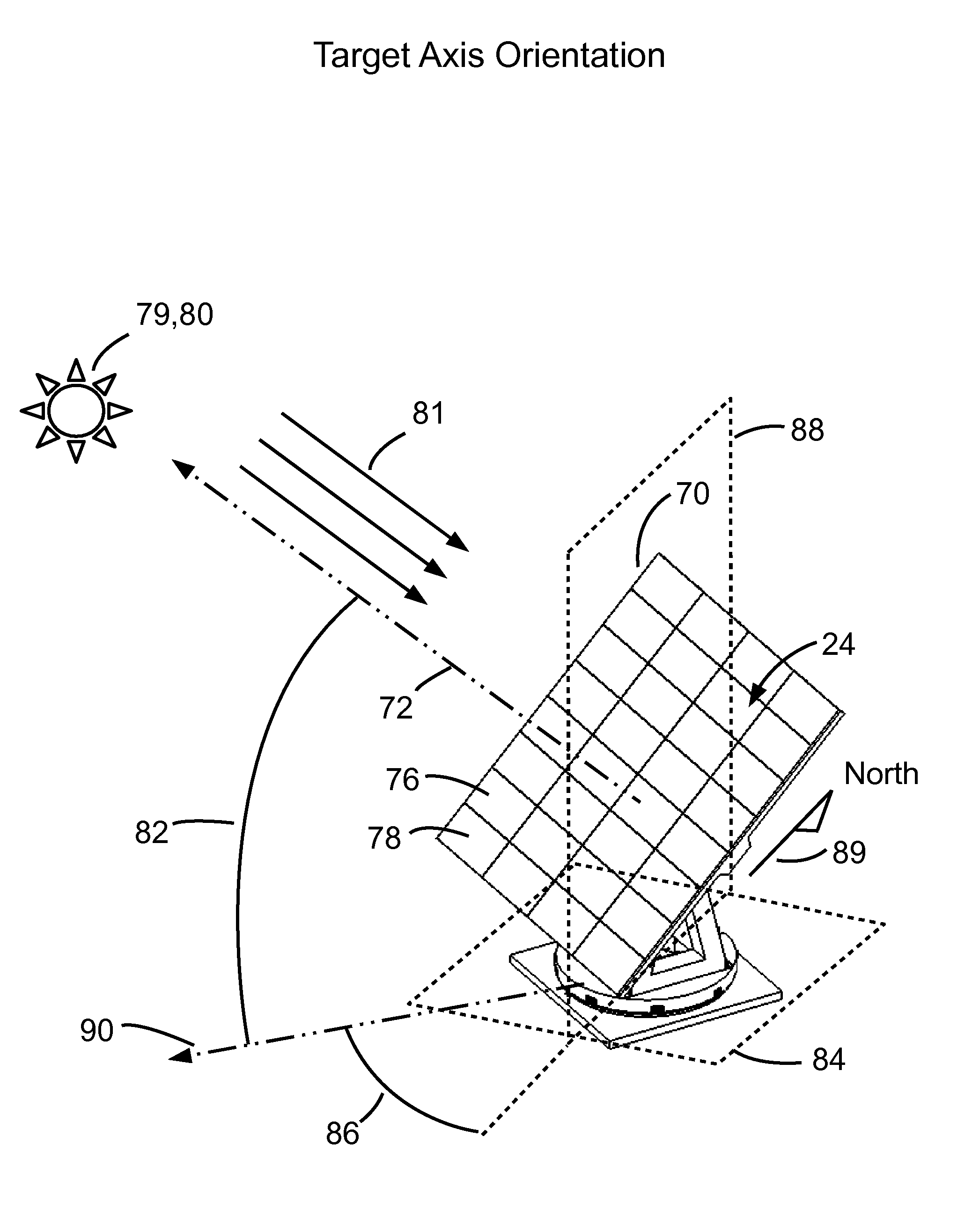
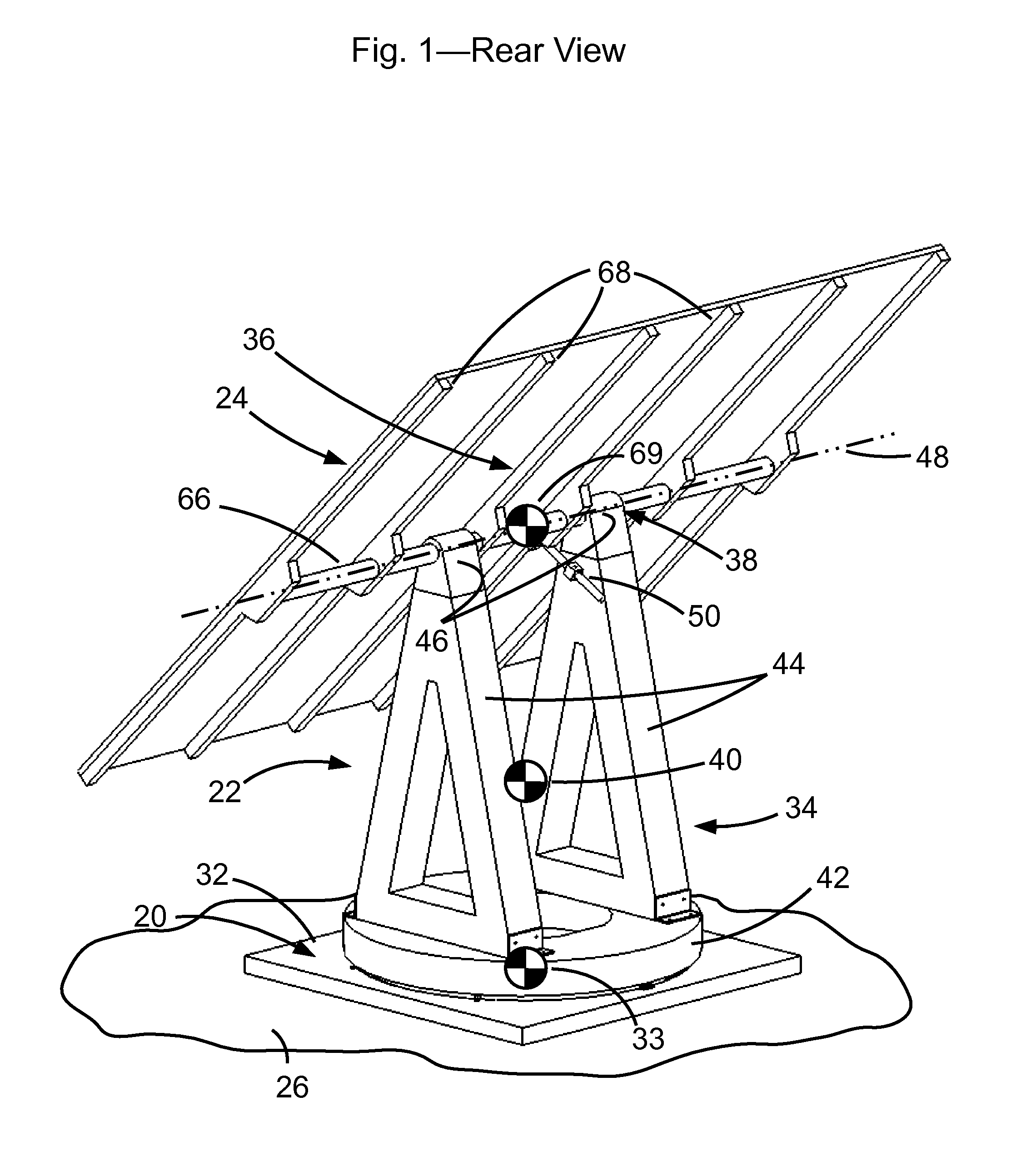
[0041]In a first embodiment, the invention is embodied as an azimuth-elevation style tracking apparatus comprising a support 20, a tracking assembly 22, and a payload assembly 24. Support 20 is mounted on a surface 26 at a contact surface 27. In this embodiment, surface 26 is realized as the Earth. In other embodiments, surface 26 could be a separate structure, such as a the roof of a dwelling.

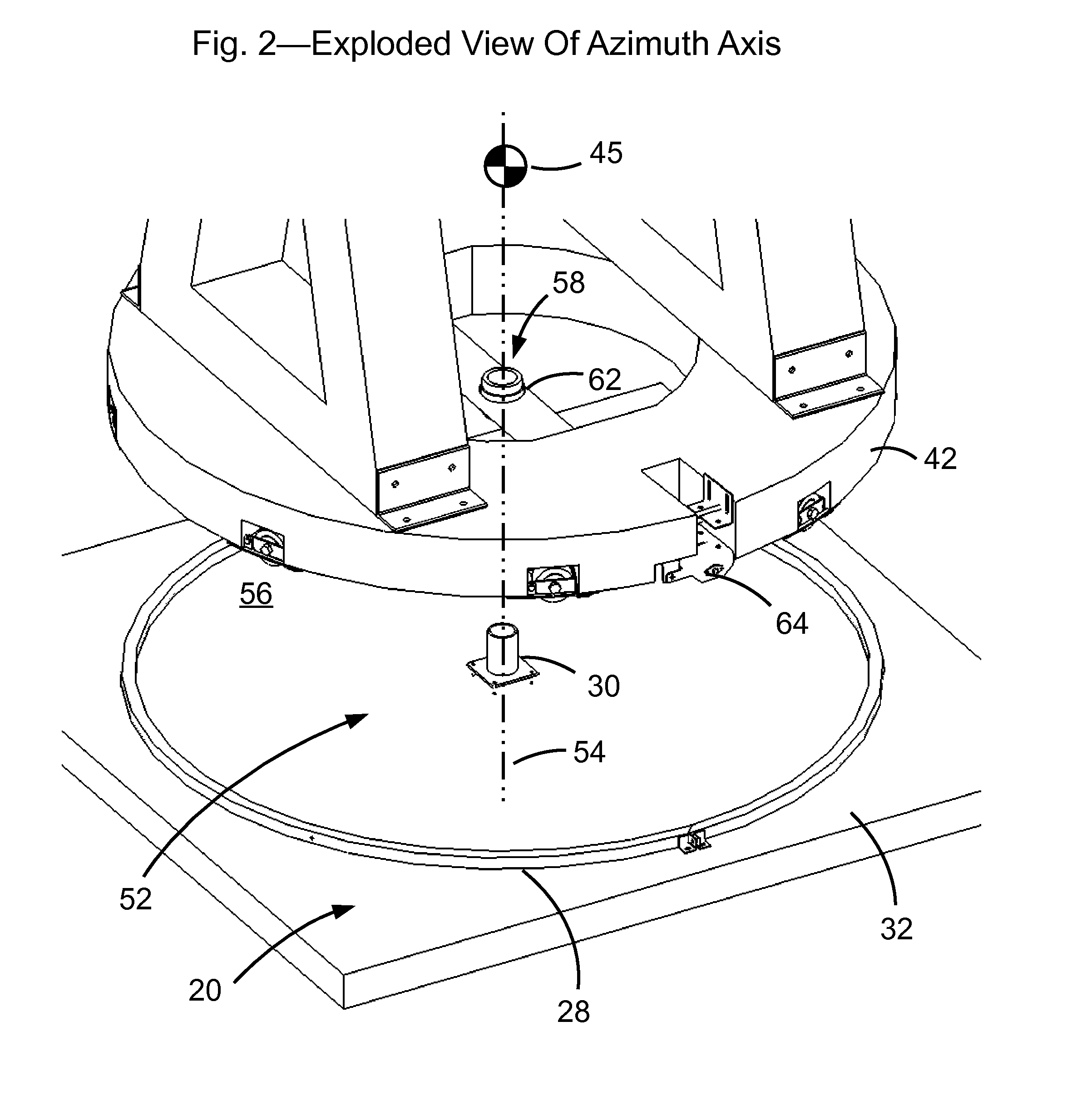
[0042]In the first embodiment, support 20 comprises a support track 28 and a center bearing support 30 mounted on a concrete slab 32. Concrete slab 32 is mounted on surface 26 and has a center of mass 33.

[0043]In other embodiments, concrete slab 32 may not be necessary, as support track 28 could be mounted directly to surface 26.

[0044]In the first embodiment, tracking assembly 22 comprises an azimuth structure 34, an elevation structure 36, and an elevation bearing set 38 by which elevation structure 36 is coupled to azimuth structure 34. Tracking assembly 22 has a center of mass 40. Azimuth s...

second embodiment

[0061]In a second embodiment, the invention is embodied as a tilt-roll style tracking apparatus comprising a support 20′ and a tracking assembly 22′ that are modified from those described in the first embodiment, and payload assembly 24′ that is similar to that described in the first embodiment. Note that the prime notation (for example 20′) indicates an element that is similar in form and function and name to an element in the first embodiment having the unprimed notation (in this case, 20). Support 20′ is mounted on surface 26′, which in this embodiment is realized as the Earth. In other embodiments, surface 26′ could be a separate structure, such as a the roof of a dwelling or a concrete surface.

[0062]In the second embodiment, support 20′ comprises two of a leg assembly 150 mounted on surface 26′ at a set of contact surfaces 152. A bearing housing 154 is affixed at the top of each leg assembly 150. Both of bearing housing 154 in combination define the outer races of a tilt bearin...


PUM


Abstract

The invention is a wind resistant celestial tracking apparatus that uses gravitational forces acting on the moving elements of the structure to provide overturning resistance. A molded self curing compound, such as reinforced concrete, is used as the structural material that provides the mass, and thus the gravitational overturning resistance that reduces or eliminates the need for a massive ballasted or dug-in foundation. The combination of these features potentially lowers cost significantly over that of tracking apparatuses found in prior art. The invention is appropriate for use in any celestial tracking application with any number of axes of motion, but is particularly useful in two axis solar energy collection systems.

Description

CROSS-REFERENCE TO RELATED APPLICATIONS[0001]Not applicableSTATEMENT REGARDING FEDERALLY SPONSORED RESEARCH OR DEVELOPMENT[0002]Not applicableBACKGROUND[0003]1. Field of Invention[0004]The present invention relates to celestial tracking apparatuses, specifically a wind resistant structure for celestial tracking apparatuses.[0005]2. Prior Art[0006]There is substantial prior art relating to the design and configuration of celestial tracking apparatuses. For example, U.S. Pat. Nos. 3,059,889 (Pottmeyer), 4,870,949 (Butler), and 6,058,930 (Shingleton) all show different configurations of one and two axis celestial tracking apparatuses.[0007]These apparatuses are generally designed to orient a payload, such as a directional radio frequency antenna, a light reflective surface, or a solar energy collection device, toward celestial objects. In the case of a radio antenna, the celestial object could be the sun, a star or planet, or a man-made orbiting satellite. In the case of a light reflec...

Claims


Application Information

Patent Timeline
IPC IPC(8): F24J2/52H01L31/042F24J2/54F24S50/20
CPCF24J2/523F24J2/525F24J2/541F24J2/542H02S20/00F24J2002/5493H01L31/0422Y02E10/47Y02E10/52F24J2/5424F24S25/10F24S25/617F24S30/425F24S30/452F24S30/455F24S2030/18H02S20/32H02S40/22
Inventor JONES, JASON CHARLESKRAFT, STEVEN MICHAEL
Owner SUNPOWER CORPORATION
Why Eureka
Try Eureka