Urea solution tank assembly

a technology of urea solution and tank, which is applied in the field of tanks, can solve the problems of reducing the service life of the tank, and achieve the effect of convenient manufacturing

Inactive Publication Date: 2009-07-30
FUEL SYST
View PDF0 Cites 64 Cited by
  • Summary
  • Abstract
  • Description
  • Claims
  • Application Information

AI Technical Summary

Benefits of technology

[0011]The various aspects of the present invention provide an advantageous storage solution for storing liquid catalysts, such as a urea solution. The storage solution is designed to be robust, easily manufactured, and able to be integrated into existing vehicles such that manufacturers of vehicles ...

Problems solved by technology

They also contribute to the formation of ac...

Method used


Image

  • Urea solution tank assembly
  • Urea solution tank assembly
  • Urea solution tank assembly

Examples


Embodiment Construction

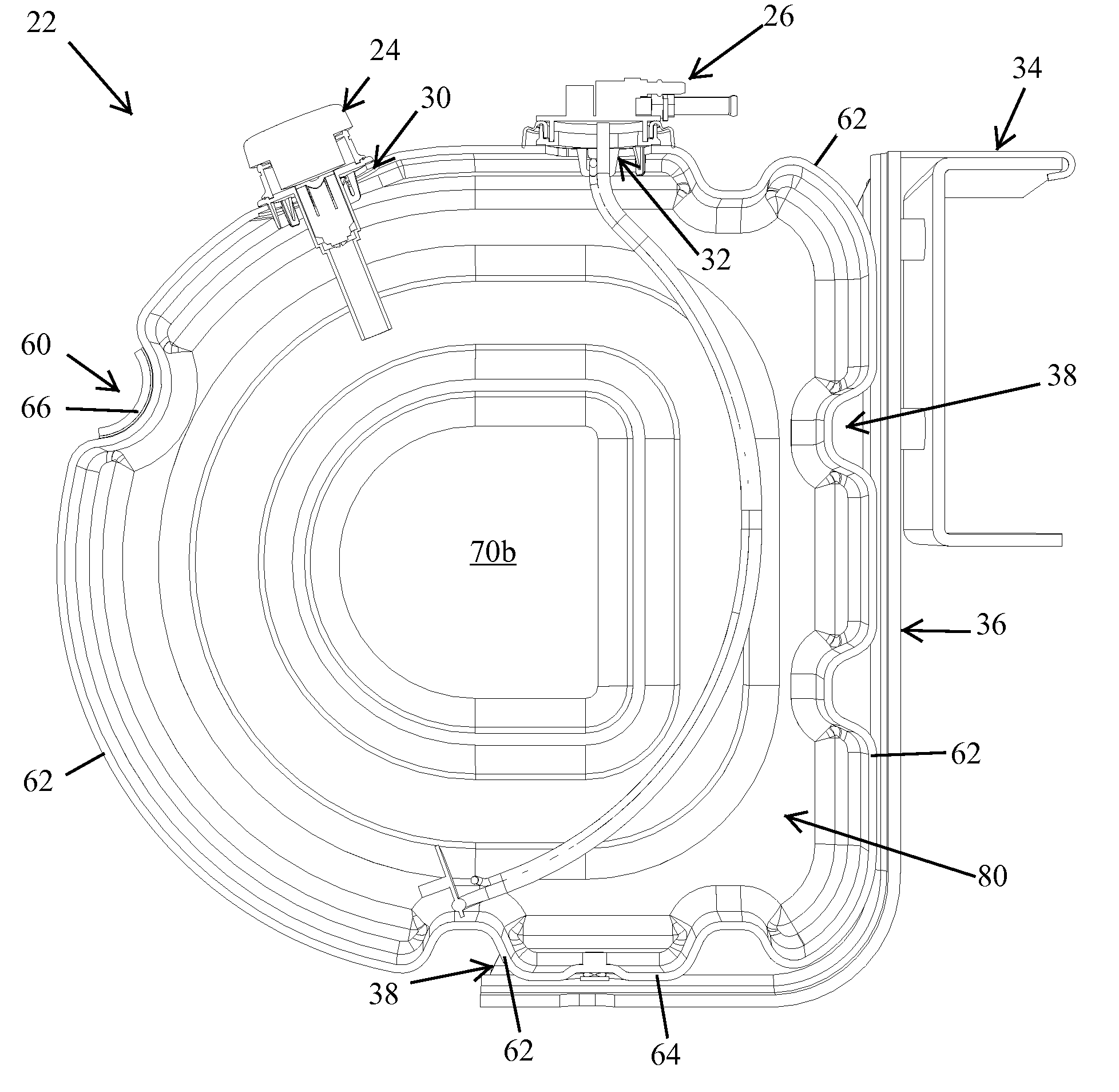
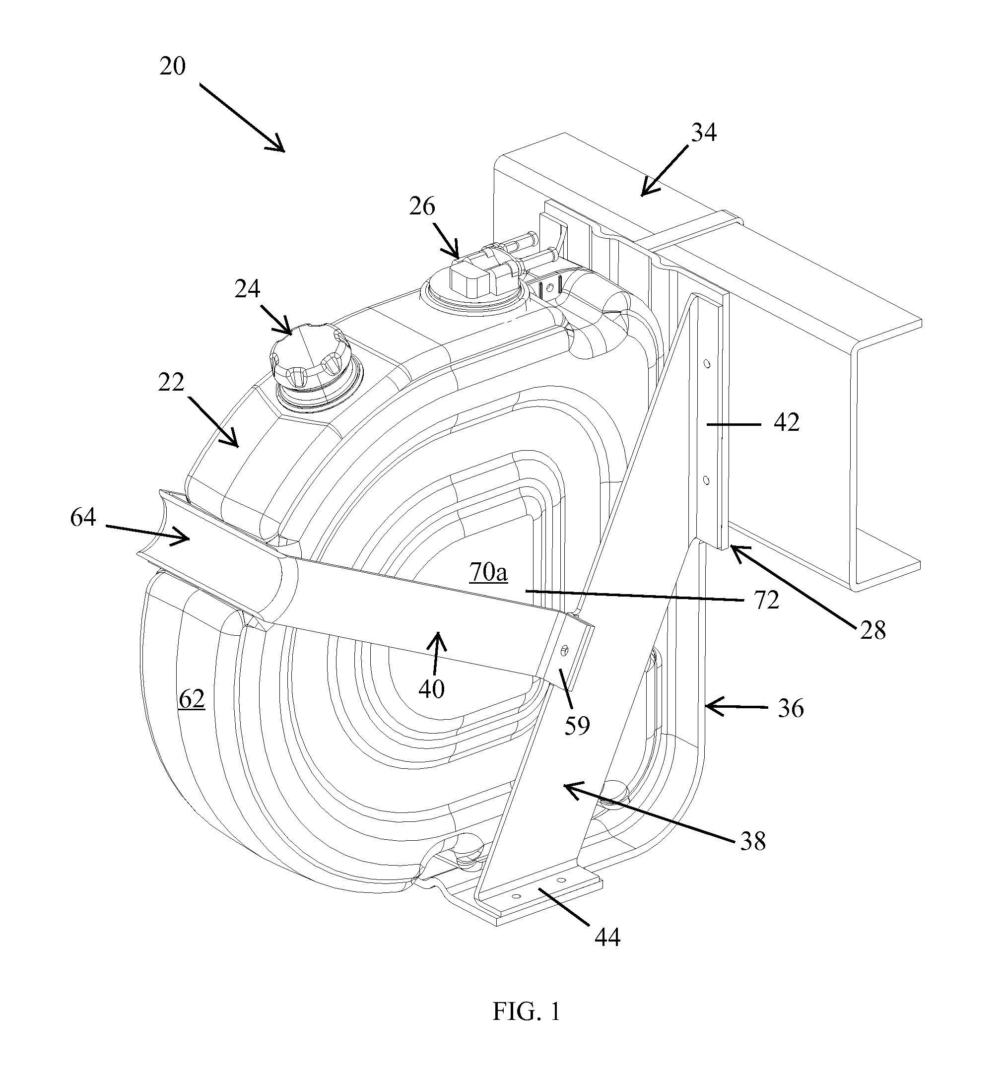
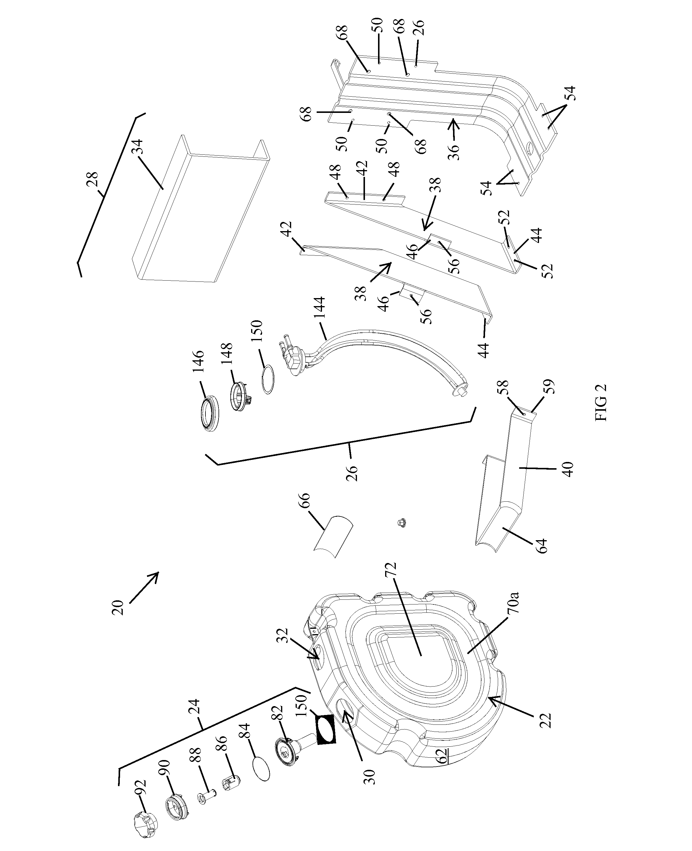
[0058]A tank assembly 20 according to a first embodiment of the present invention is illustrated in FIG. 1. Tank assembly 20 includes a tank 22 for storing a urea solution, a filler tube assembly 24, a sensor unit assembly 26, and a bracket system 28. Filler tube assembly 24 is adapted to allow urea solution to be delivered to tank 22 through a first aperture 30 (FIG. 2). Sensor assembly 26 is adapted to sense the level of urea solution within tank 22, as well as to allow urea solution to be pumped out of tank 22 through a second aperture 32 for delivery to a selective catalyst reduction (SCR) system (not shown), which may be located on a motorized vehicle as part of a nitrogen oxide (NOx) emission reduction system for the motorized vehicle. Alternatively, in at least one embodiment, the SCR system may be utilized to help reduce the emissions from a stationary source of NOx, and tank assembly 20 may thus be mounted in a stationary location, rather than on a motorized vehicle. Regard...


PUM


Abstract

A tank for storing urea solution and a tank assembly for storing disparate fluids, such as diesel fluid and urea solution, are disclosed. The tank may further include a filler assembly and/or a sensor assembly, either of which are adapted to be connected to the tank without the use of separate fasteners, The tank assembly may include a reservoir and a sensor for automatically diverting non-conforming urea solution to the reservoir. A recess may be defined in the tank body in order to accommodate a strap for securing the tank to the frame of vehicle. The tank may include parallel sidewalls that include a projection on one and a corresponding indentation on the other in order to allow the tanks to be easily stacked during assembly.

Description

CROSS-REFERENCE TO RELATED APPLICATIONS[0001]This application claims priority to commonly-assigned, U.S. provisional application Ser. No. 61 / 012,484, filed Dec. 10, 2007 by applicants Robert H. Versaw Jr. et al. entitled UREA SOLUTION TANK ASSEMBLY, the complete disclosure of which is hereby incorporated herein by reference.BACKGROUND OF THE INVENTION[0002]The present invention relates to tanks for storing urea solution, and more particularly to tanks that may be utilized in conjunction with a selective catalyst reduction (SCR) system that reduces the nitrogen oxide (NOx) emissions of a motorized vehicle.[0003]Nitrogen oxides are one of the main components responsible for the generation of ground level ozone. They also contribute to the formation of acid rain, and have other deleterious side effects. The Environmental Protection Agency (EPA) tracks the emissions of nitrogen oxides, along with five other common pollutants, and sets national ambient air quality standards for NOx. NOx ...

Claims


Application Information

Patent Timeline
IPC IPC(8): B65D88/12B65D25/04B65D90/48
CPCB60K13/04B60K2015/03348F01N3/2066F01N2610/1406Y02T10/24F02B3/06F02M37/0082F02M37/0088F01N2610/1413Y02T10/12Y02A50/20
Inventor VERSAW, JR., ROBERT H.WRIGHT, RICHARD W.POWNEY, ROBERT L.
Owner FUEL SYST
Why Eureka
Try Eureka