Detection of heavy oil using fluorescence polarization

a technology of fluorescence polarization and detection of heavy oil, which is applied in the direction of luminescent dosimeters, optical radiation measurement, instruments, etc., can solve the problems of increasing the problem of pollution in lakes and oceans, exacerbate the problem of oil spills, and many accidents occur annually, so as to prevent interference from ambient sunlight

Active Publication Date: 2009-07-30
EIC LAB
View PDF9 Cites 25 Cited by
  • Summary
  • Abstract
  • Description
  • Claims
  • Application Information

AI Technical Summary

Benefits of technology

[0017]In some embodiments, the method further comprises measuring the intensities of the vertically and horizontally polarized components. The method may include separating the collected fluorescence from the excitation light and / or the step of recording the intensities of the vertically and horizontally polarized components as spectra. In some embodiments, interference from ambient sunlight is prevented.

Problems solved by technology

Increased consumption and transportation of oil and its products exacerbate the problem of pollution in lakes and oceans.
Even with strict regulation of oil transportation, accidents leading to oil spills still occur frequently.
Indeed, numerous accidents occur annually, with thousands of tons of oil being spilled into seas, contaminating marine environments and endangering marine ecology.
These oil residues are typically rich in polynuclear aromatic hydrocarbons (PAHs), which are toxic to aquatic life.
Oil spills in coastal waters, harbors, and oil terminals are especially dangerous and necessitate a rapid response when they occur in order to prevent contamination of marine habitats.
A number of known methods for detecting oil spills are mostly limited to surface oil.
However, airborne fluorescence methods are generally unable to detect deep underwater oil contaminants.
Furthermore, fluorescence methods are susceptible to interference from other fluorophores in water, such as humic compounds, chlorophyll and other plant pigments.
Because of the similarity in oil and other natural sediments, these methods, while providing a rapid survey, generally require confirmation by further sampling and analysis, and therefore do not offer real-time results.
Sonar frequently does not provide sufficient contrast with the sedimentary sea floor.

Method used


Image

  • Detection of heavy oil using fluorescence polarization
  • Detection of heavy oil using fluorescence polarization
  • Detection of heavy oil using fluorescence polarization

Examples


example 1

[0035]Laboratory Tests. A laboratory setup suitable for measuring the fluorescence polarization spectra of various test samples was constructed. The excitation source was a 473 nm diode-pumped solid-state laser. The laser output was collimated by a 25 mm diameter f2 lens, transmitted through a linear polarizer oriented vertically, transmitted through a 45° dichroic filter, and then focused by a 25 mm diameter f2 lens onto the sample. The fluorescence emission from the sample was collected and collimated by the same lens, reflected off the dichroic filter at 90°, transmitted through a variable polarizer, and then focused by a 25 mm diameter f2 lens onto a 200-micron core optical fiber. The distal end of the optical fiber was coupled to a spectrograph that disperses the fluorescence signal into discrete wavelengths that are detected with a CCD detector. The vertical and horizontal fluorescence polarization spectra were recorded sequentially by manually rotating the variable polarizer ...

example 2

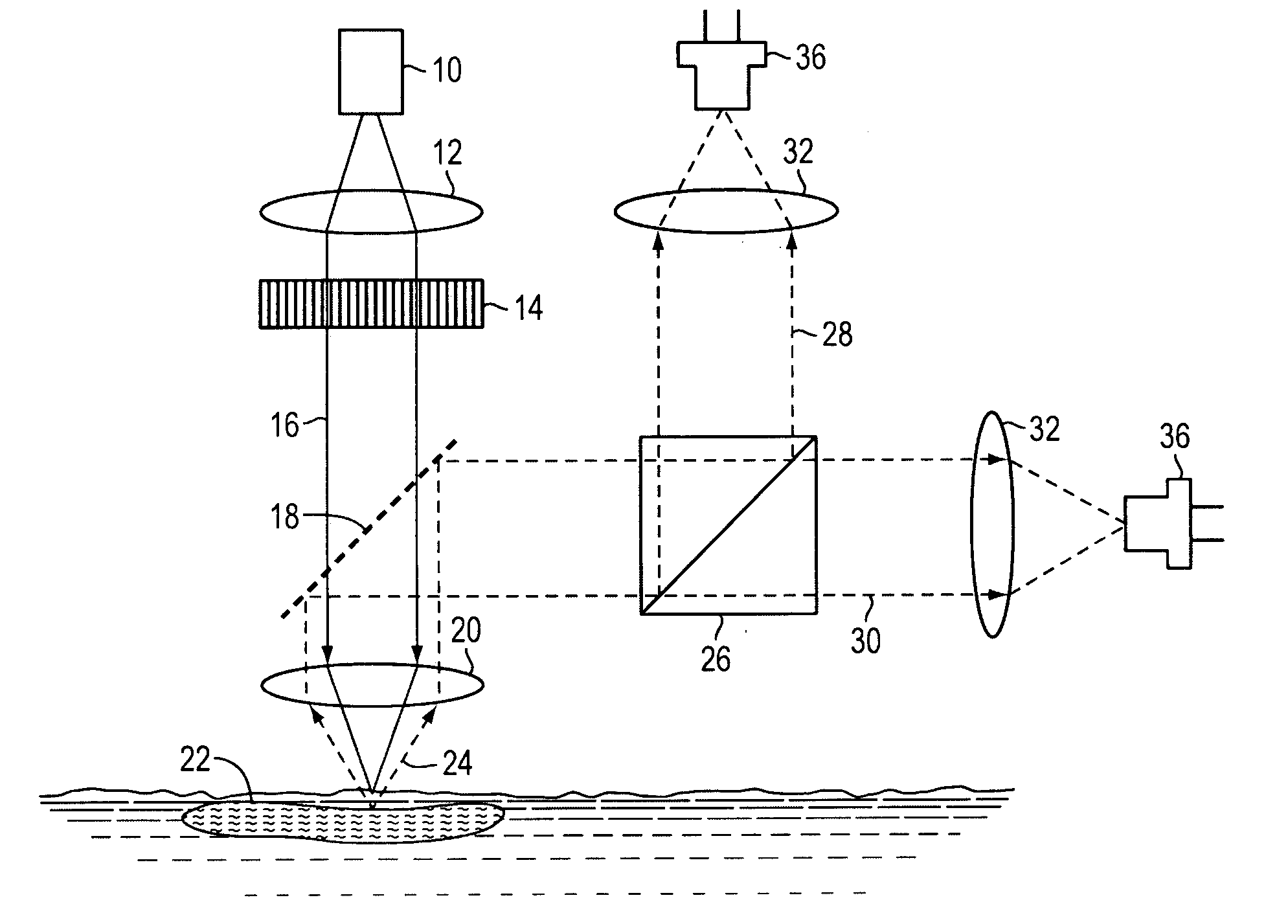
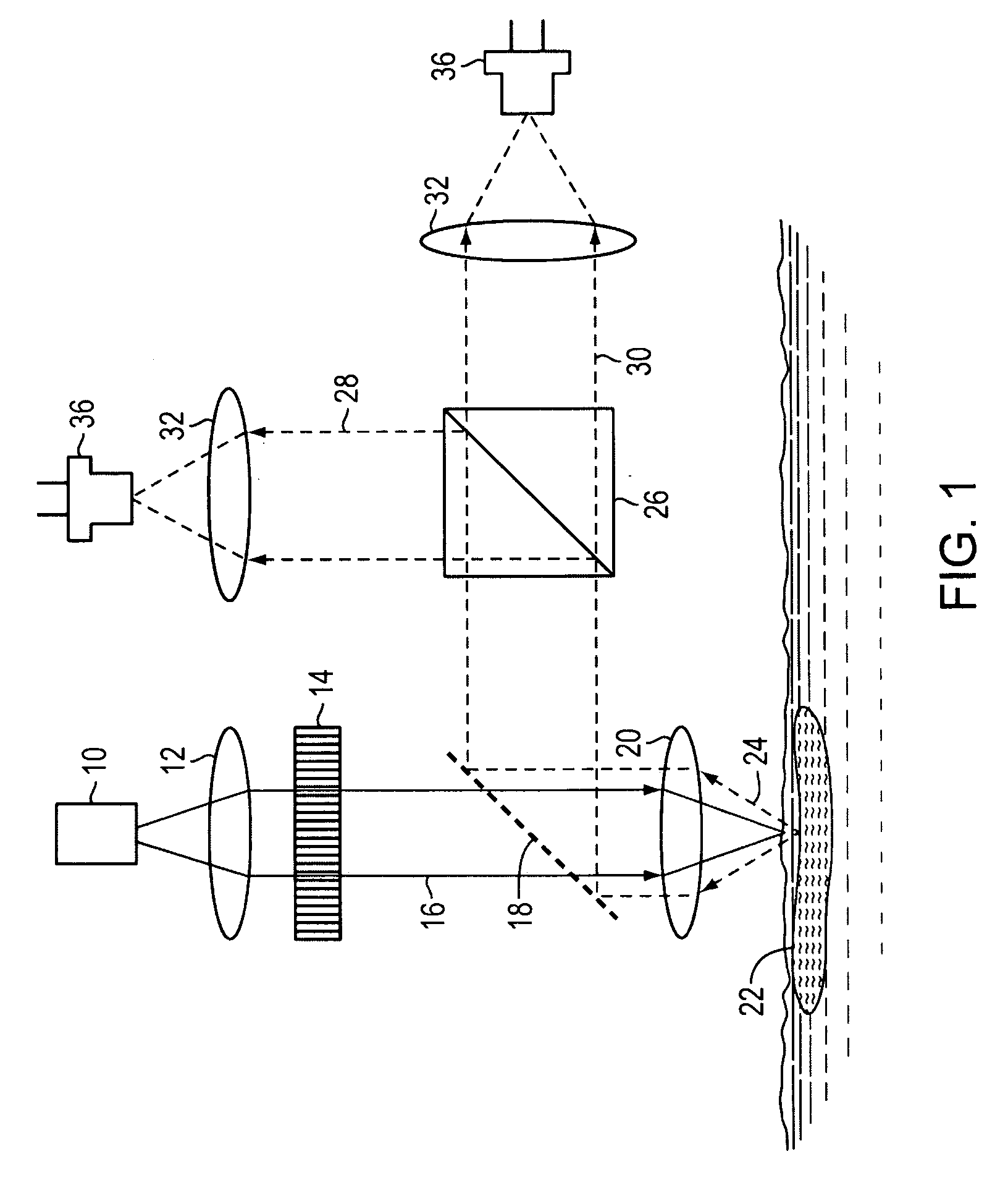
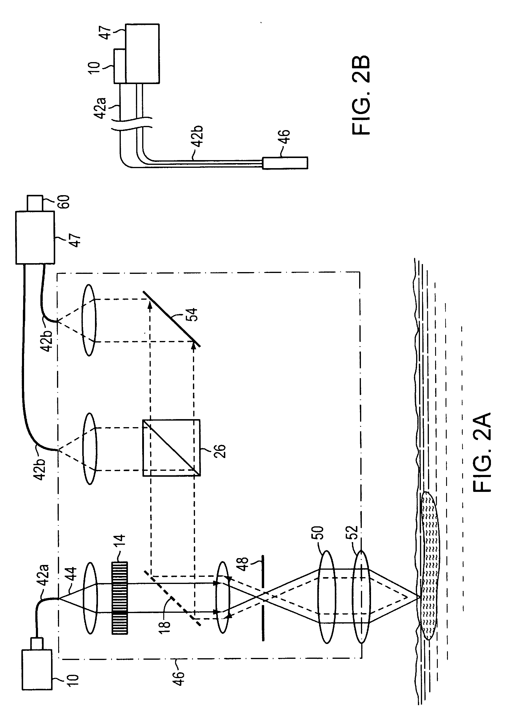
[0040]Field Tests. For field testing, a fluorescence polarization probe of configuration similar to that illustrated in FIG. 1 was mounted in a waterproof enclosure. The main components of the probe were a fiber-optic fluorescence polarizer and a telescopic focusing / collection optic. The fiber-optic fluorescence polarizer utilized three miniature optical trains (laser excitation, perpendicular FP collection, and parallel FP collection) arranged in a backscattering light-collection probe configuration. The probe telescope was a simple refractor telescope having a 50 mm diameter, 100 mm focal length objective lens and a 9 mm diameter, 11 mm focal length eyepiece. The telescope was used to focus the laser beam onto the sample and also to collect the fluorescence emitted by the sample. With the telescope as the front optical component of the fluorescence polarization probe, the probe in this example can detect fluorescence signals from fluorescent samples less than one meter to several ...


PUM


Abstract

Viscous oil residues are located based on fluorescence polarization. Methods and apparatus in accordance with the invention may be integrated with autonomous and remotely operated undersea vehicles to map the location of oil spills.

Description

RELATED APPLICATION [0001]This application claims priority to, and the benefits of, U.S. Provisional Application Ser. No. 61 / 024,337, filed on Jan. 29, 2008, the entire disclosure of which is hereby incorporated by reference.GOVERNMENT RIGHTS [0002]This invention was made with Government support under Contract No. HSCG32-07-C-R00013 awarded by the U.S. Coast Guard Research and Development Center. The Government has certain rights to this invention.FIELD OF INVENTION [0003]This invention relates to devices and methods for detecting the composition and location of viscous oil residues such as oil spills or oil deposits in subsurface locations, particularly on the floor of oceans, lakes and other aquifers.BACKGROUND OF INVENTION [0004]Increased consumption and transportation of oil and its products exacerbate the problem of pollution in lakes and oceans. Even with strict regulation of oil transportation, accidents leading to oil spills still occur frequently. Indeed, numerous accidents...

Claims


Application Information

Patent Timeline
Patent Type & Authority Applications(United States)
IPC IPC(8): G01T1/169G01J4/00G01J1/58
CPCG01J3/4406G01J3/447G01N2021/945G01N21/94G01N21/6445
Inventor BELLO, JOB M.
Owner EIC LAB
Why Eureka
Try Eureka